The steps to complete the drawing of this exercise, will now be executed and described below:
•Create construction crosshairs for guidance
oClick on the ![]() Create construction lines icon and select the
Create construction lines icon and select the ![]() Create a construction cross tool to aid in drawing the figure with dimensions specified. Follow the instructions at the bottom of the screen.
Create a construction cross tool to aid in drawing the figure with dimensions specified. Follow the instructions at the bottom of the screen.
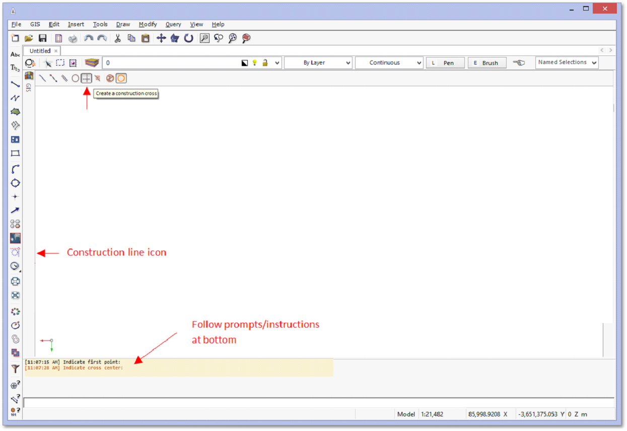
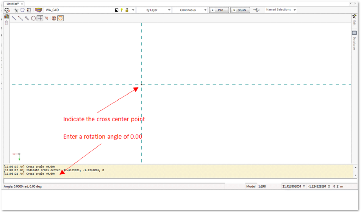
oSelect the centre point of the construction cross. Enter an angle of 0.00. Right-click to finish procedure:
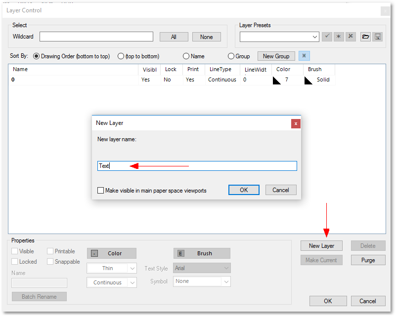
•Create new layer: Text
oClick on the ![]() Edit layers icon. The Layer Control box pops up. Click on the New Layer button and create a new layer called “Text”.
Edit layers icon. The Layer Control box pops up. Click on the New Layer button and create a new layer called “Text”.
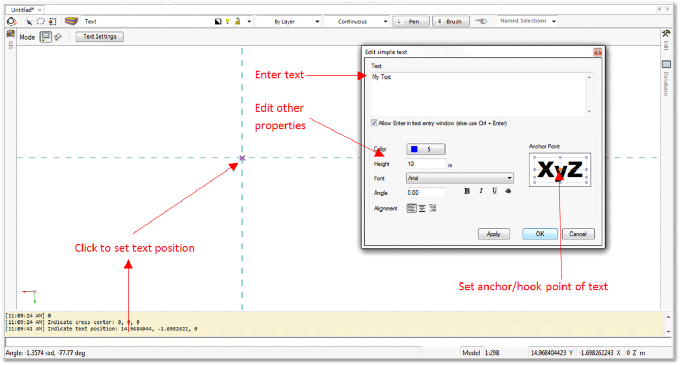
oMake sure Text layer is the current layer (Tip: press escape to cancel all selections – the name displayed in the layer name box is the current layer). Click on the Insert Text icon. Indicate the text position. Choose the centre of the cross.
•Input text with centre of text as hook point on cross point
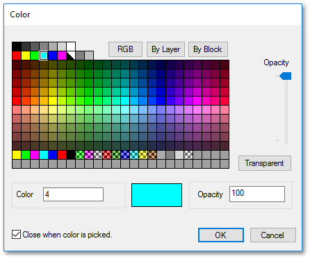
•Set text colour as blue (5) and height of 10 m
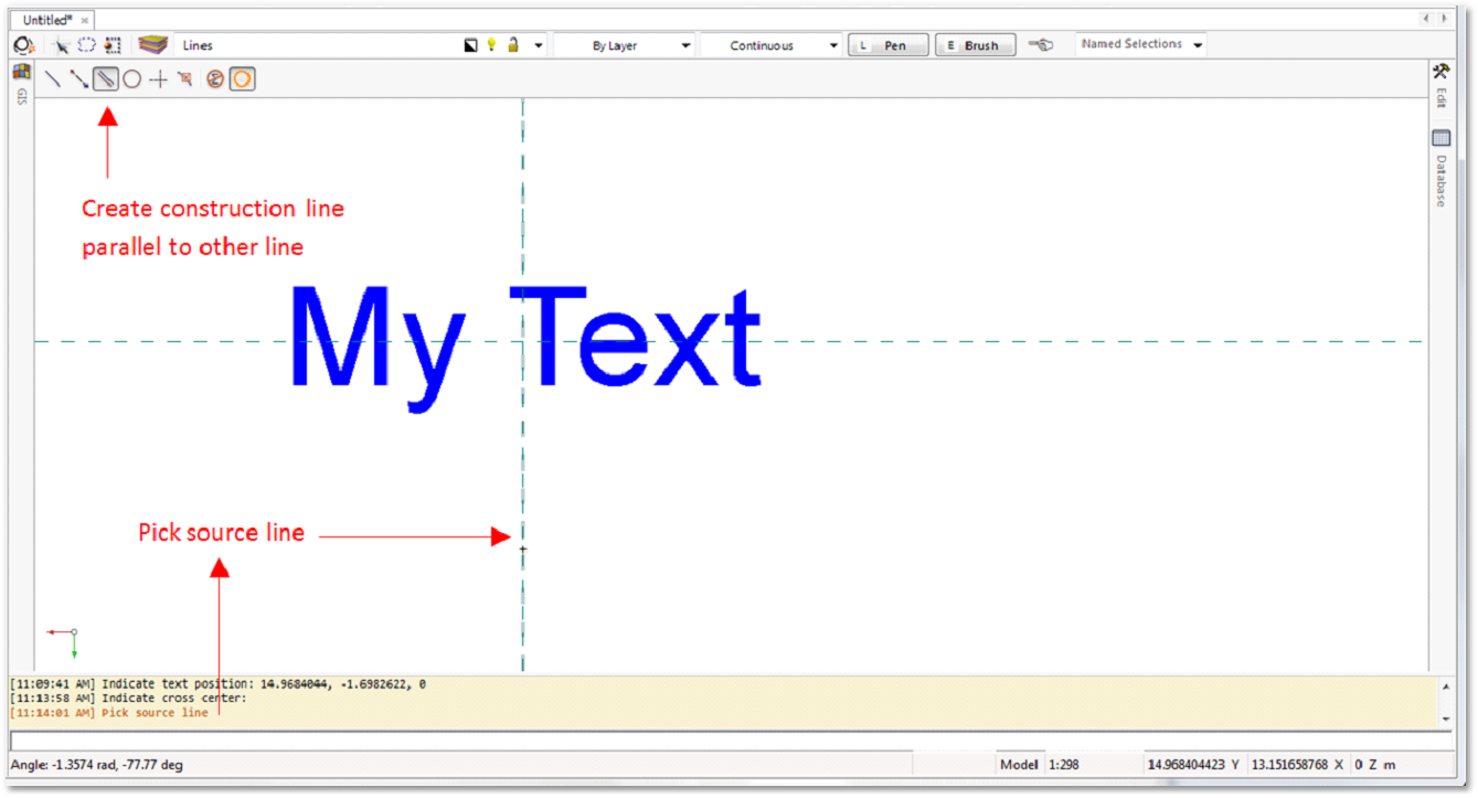
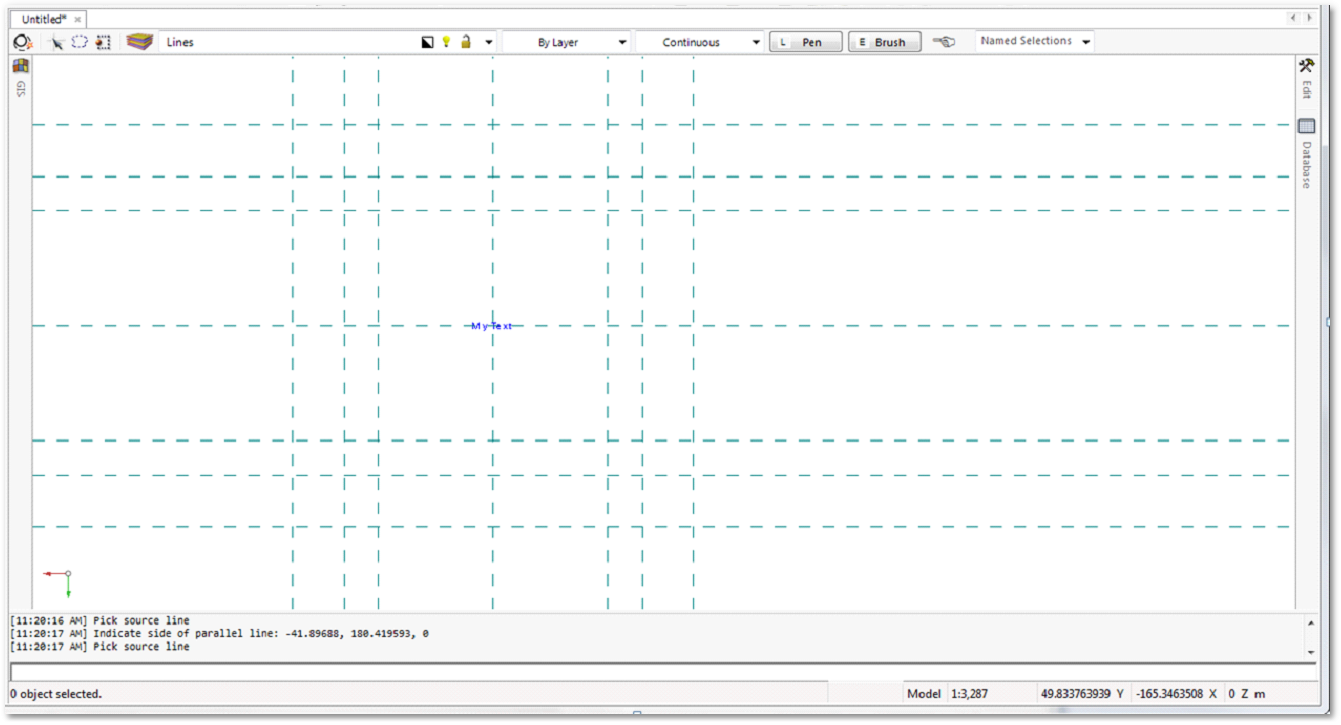
•Create additional constructions lines
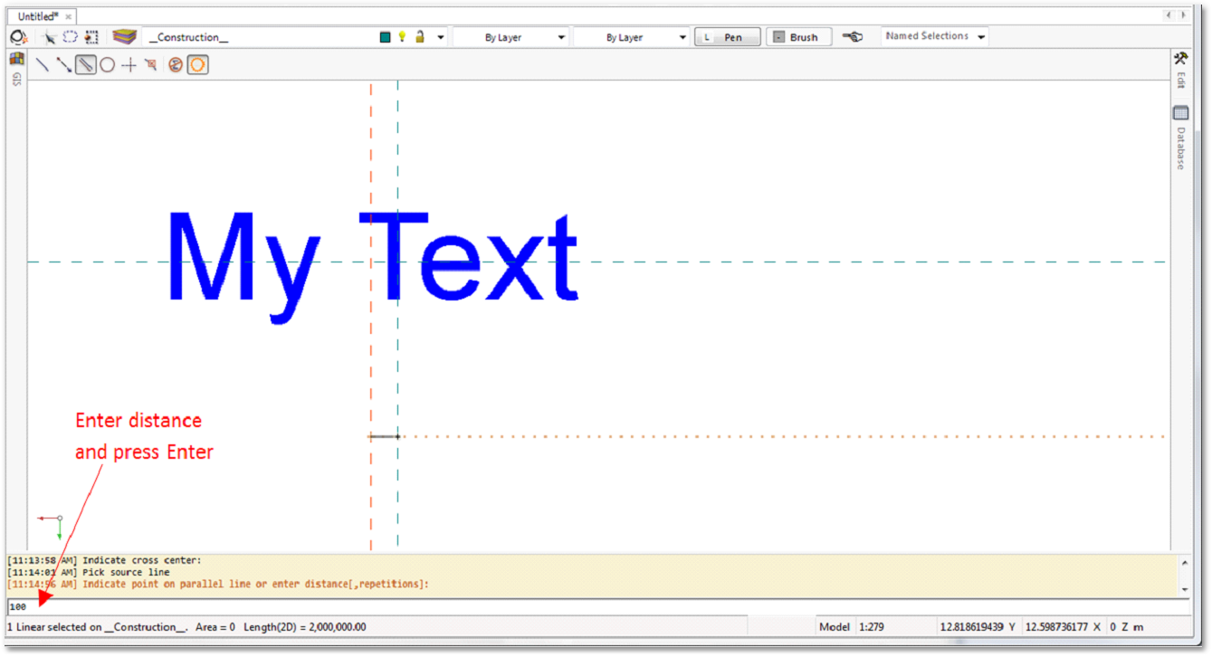
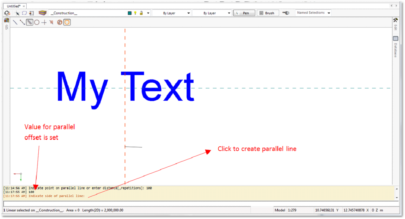
oNow create additional construction lines to draw other entities. Use the parallel lines for this example. Pick the source line. Enter the distance of the desired offset. Then click to the side of the line you want to create a parallel line (option for creating several repetitions).
oIt might be required to zoom out to see the construction line you created:
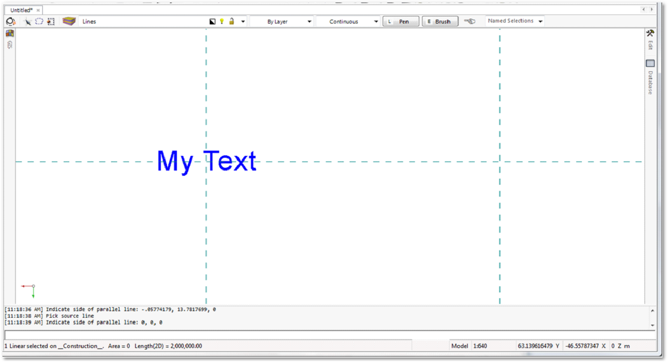
oContinue to create construction lines according to the dimensions of the exercise:
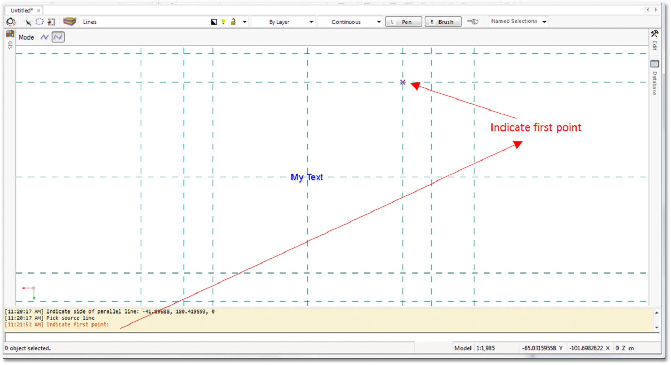
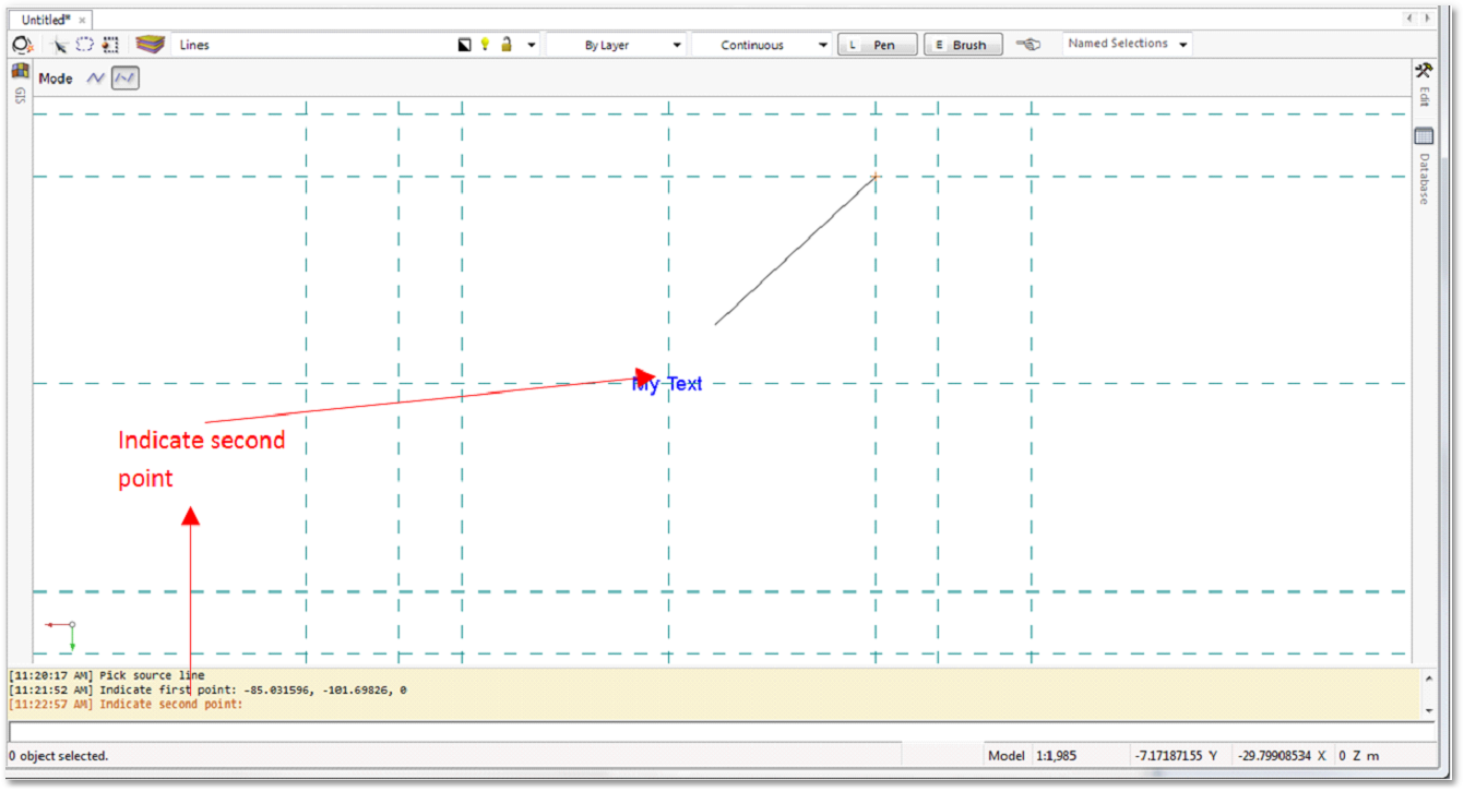
•Create new layer: Lines
oClick on the Create a line icon and draw lines.
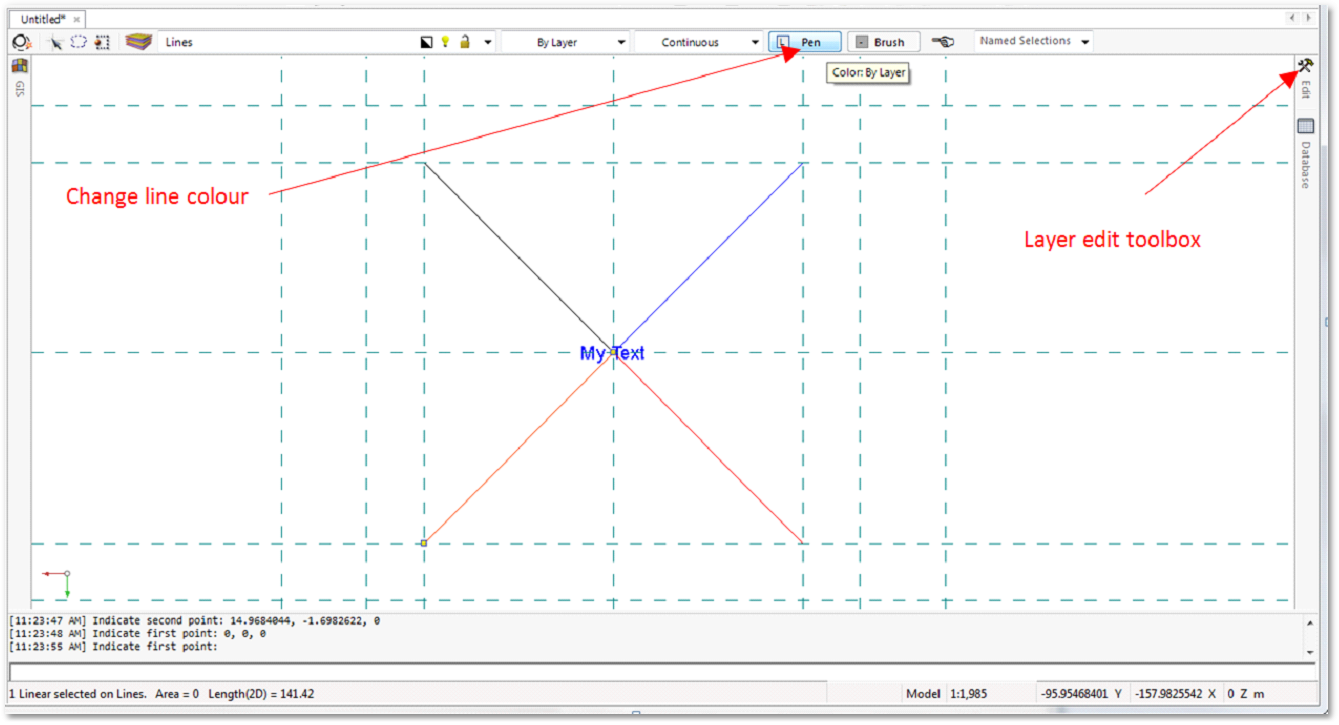
oCreate all the lines. Edit the line colours as indicated. Select the line and use the editor toolbox or clicking the change line colour button:
oSelect the Colour and Opacity
•Create new layer: Polylines
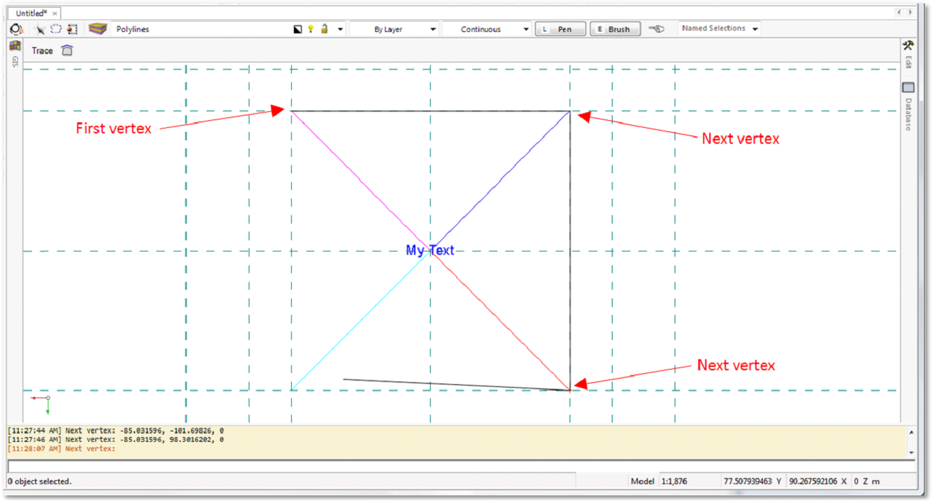
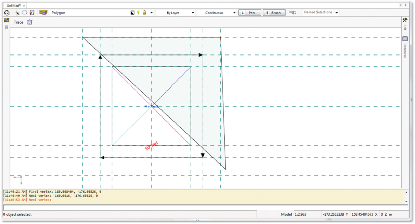
oCreate a polyline. Select the first vertex (starting point) and continue to draw the polyline by left-clicking to create more vertices. Right-click to end the procedure (Tip: clicking on the first vertex point will also end the procedure and create a closed polyline which can be converted to a polygon):
•Copy and paste text, edit text
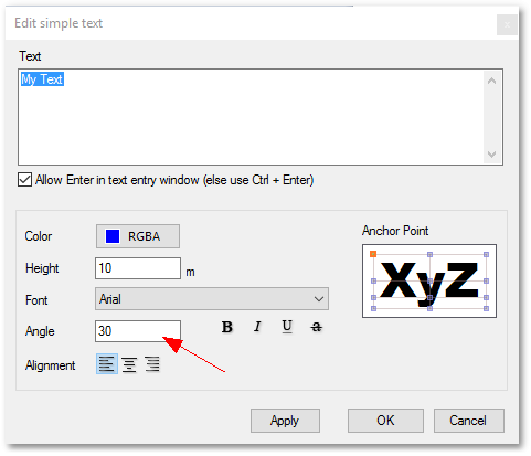
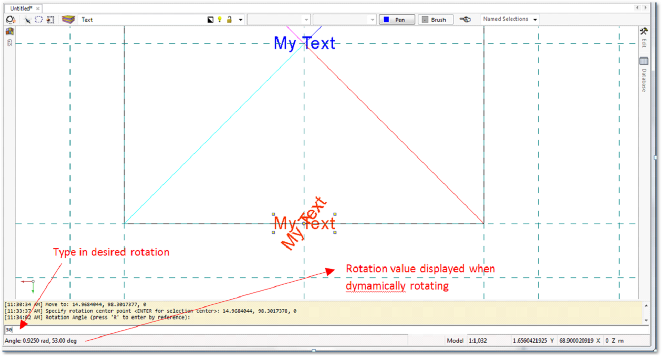
oCopy the "My Text" and move it to the bottom/southern line. Rotate the text by 30 degrees. For text, the text setting can merely be changed, other entities need to be rotated by selecting a reference point. Both methods are described below.
oEdit Text:
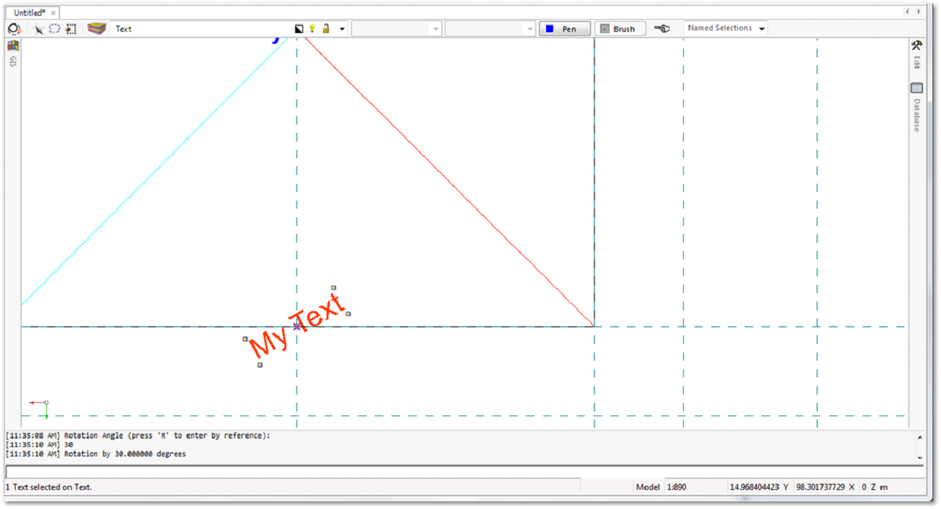
oRotate: Select text. Click on the “Rotate objects” icon. Select the reference point:
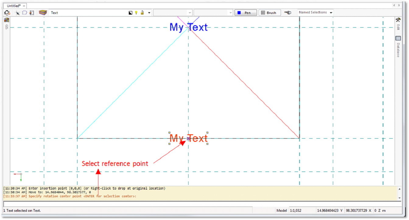
oEnter the rotation degrees and press Enter or dynamically rotate around object and left click:
oChange the text colour to red:
•Create new layer: Arrows
oDraw arrows as indicated. Click on the ![]() Insert arrow icon. Select the arrow head dimensions before drawing the arrow or by editing the feature afterward through the editor toolbox. Arrows are like polylines with special features for the arrow head and tail.
Insert arrow icon. Select the arrow head dimensions before drawing the arrow or by editing the feature afterward through the editor toolbox. Arrows are like polylines with special features for the arrow head and tail.
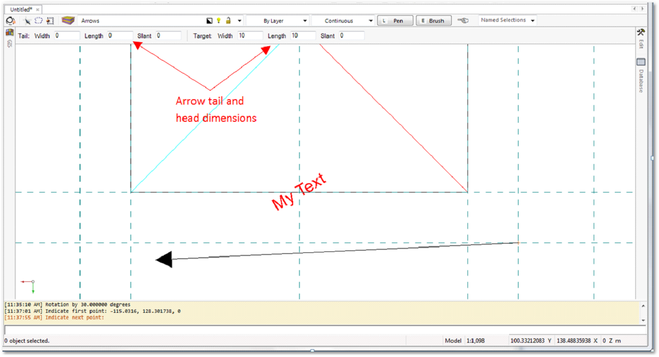
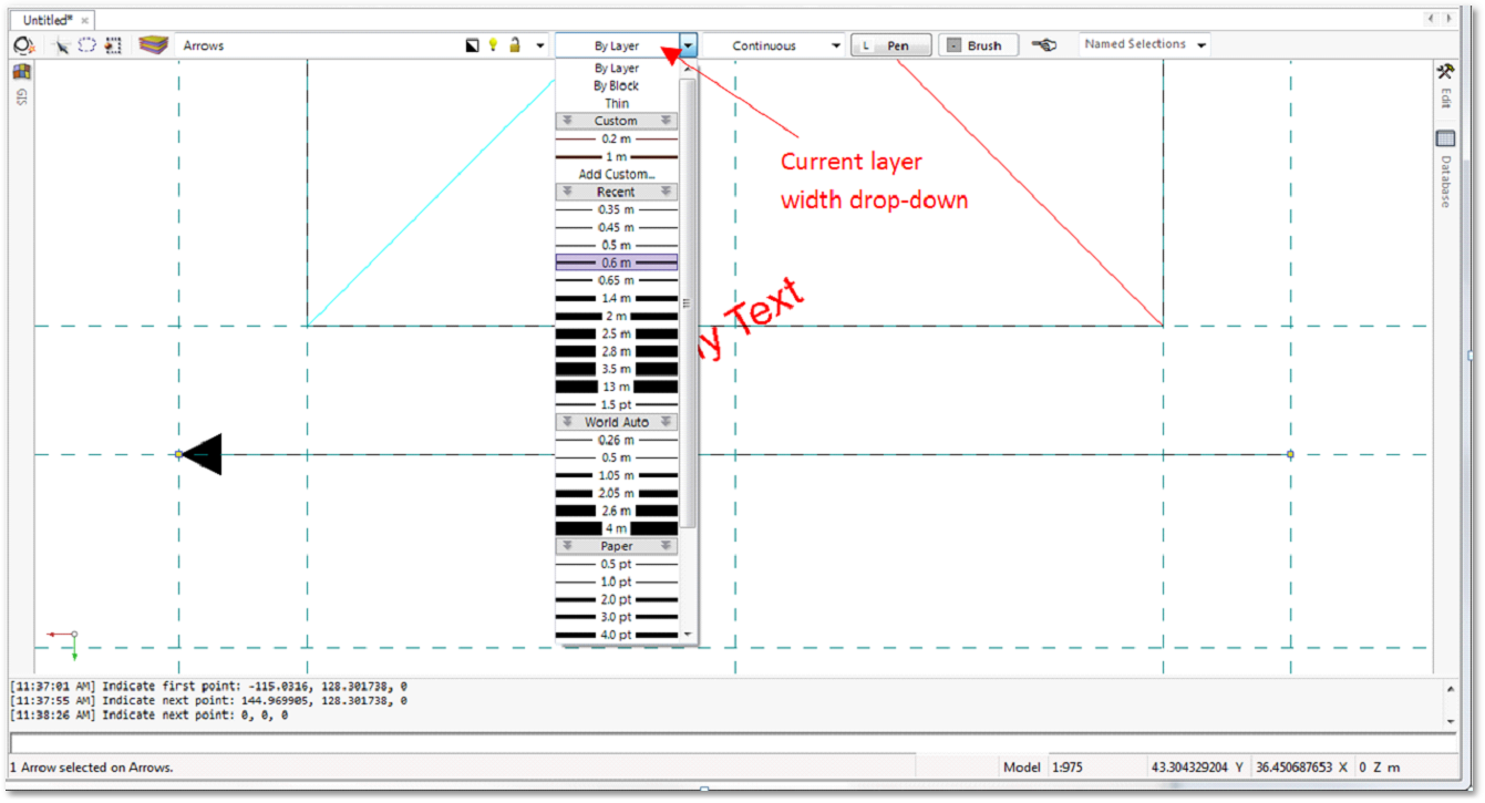
oEdit the width of the arrow. Select the arrow entity and change the width from the Current line width drop-down or from the editor toolbox.
•Create new layer: Polygon
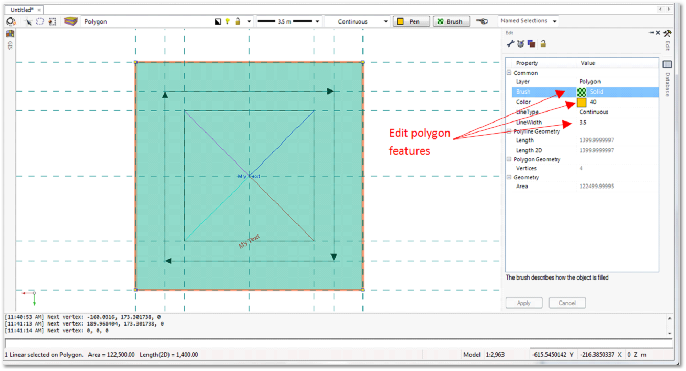
oDraw a filled polygon as indicated (using the ![]() Create a polygon tool).
Create a polygon tool).
oSelect the polygon and edit its features.
•Create new layer: Circle
oCreate a circle with the dimensions indicated:
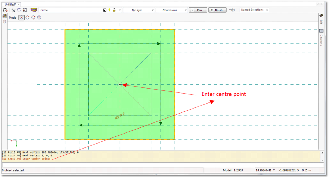
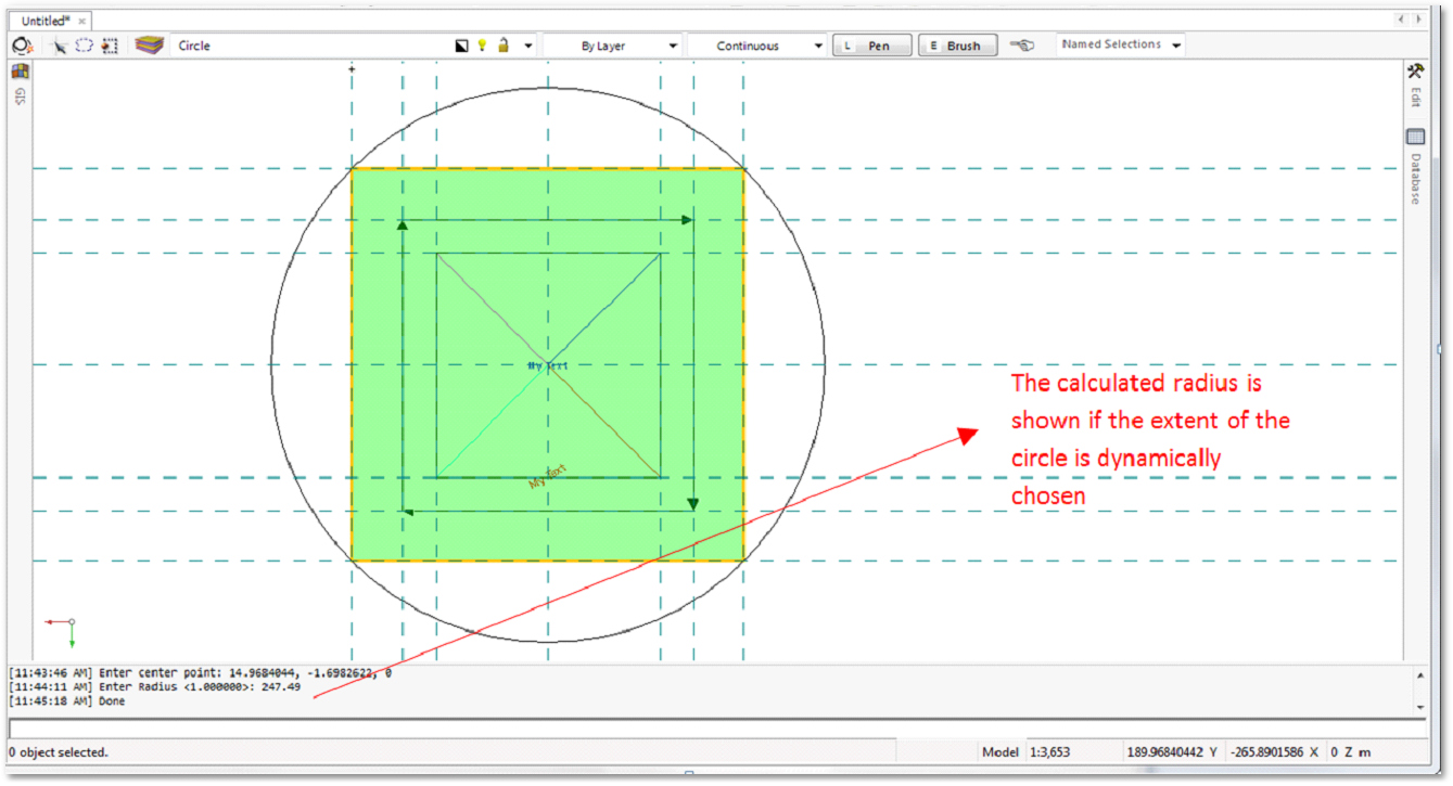
oType in the desired radius if known and press Enter. The extent of the circle can be chosen dynamically by selecting a point. The radius of the circle will be shown:
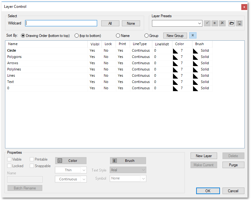
•Adjust layer order
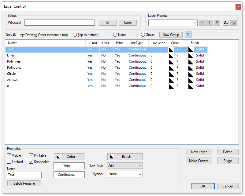
oOpen the Layer Control box. The order of the layers can be adjusted by selecting a layer and dragging it to its new position (first layer is top most).
Before:
After:
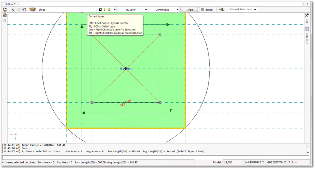
•Adjust the lines on the Lines layer
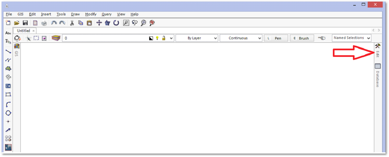
oAdjust the widths of all the entities on the Lines layer. Select an entity on the Lines layer. Hover with the mouse pointer next to the name of the layer (Lines) in the layer name drop-down and right-click to select all entities on the layer. Open the Edit properties box, by clicking on the Edit fly-in menu at the top right. In the Edit properties box, edit the widths of a line entity to 1.4 m. Since all lines are selected on the layer, they will all receive automatically the same updated 1.4 m line width.
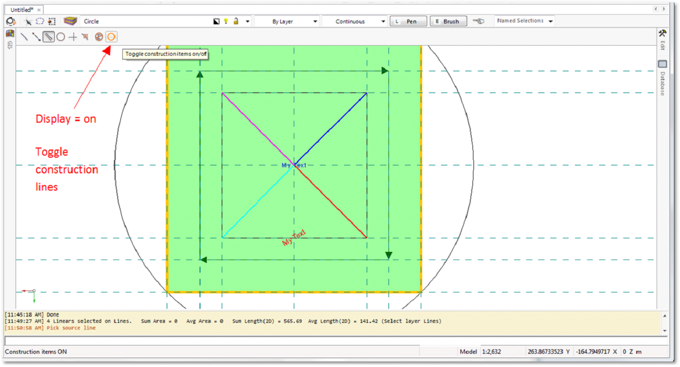
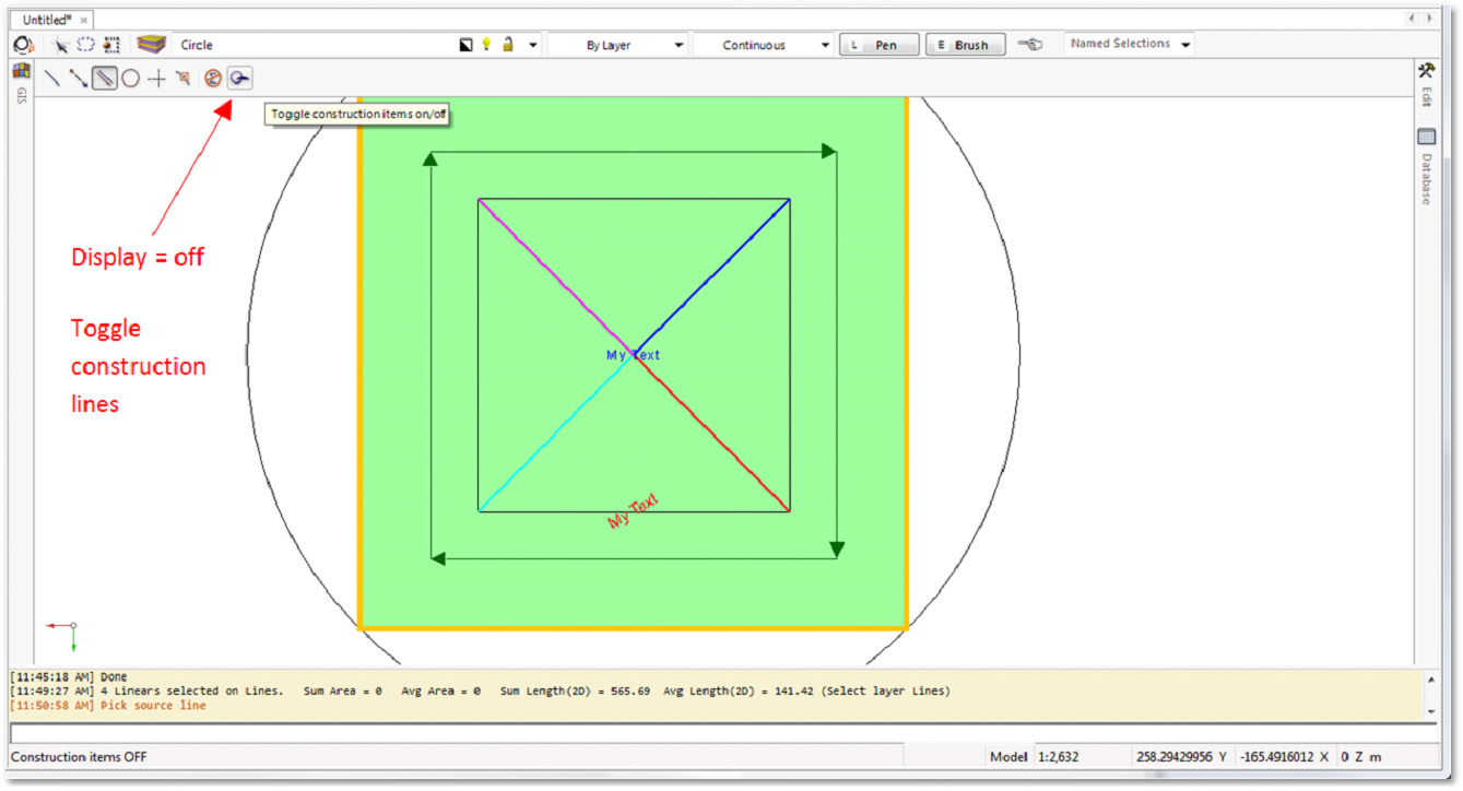
•Removing construction lines
oYou can toggle the construction lines on/off or delete them if no longer necessary:
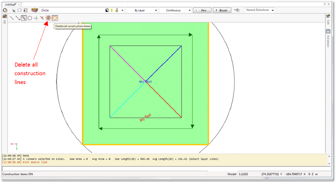
oDelete all construction lines if no longer necessary:
•Save drawing
oWe are finished now with the Advanced CAD Exercise. If you want, you can save your work by selecting File > Save Drawing or by clicking on the ![]() Save Drawing icon. Both methods will open a file Save As dialog box where you can specify a folder and file name (*.abd) for the current drawing to be saved. Please note that saving to a CAD file format other than *.abd is not supported in the evaluation/demo version of the software.
Save Drawing icon. Both methods will open a file Save As dialog box where you can specify a folder and file name (*.abd) for the current drawing to be saved. Please note that saving to a CAD file format other than *.abd is not supported in the evaluation/demo version of the software.
Before continuing with the next tutorial, it is recommended to exit and restart the program to start with a clean slate.