The first step in this exercise is to load in a background CAD drawing (which currently has a non-standard co-ordinate system), and to then fix it to the proper co-ordinate system, which will be applied when creating the model.
Select CAD > Open Drawing, and then open the drawing file labelled Wadiso 6 - Tutorial 2 Drawing.abd, which was installed on the Documents\GLS\Wadiso\ directory, together with the program. Then, select View > Zoom to Drawing Extents to zoom to the entire drawing extent. The following image shows the basic composition of this drawing, with cadastral layout, 2 points with known co-ordinates (in the proper co-ordinate system for the area depicted), and pipelines.
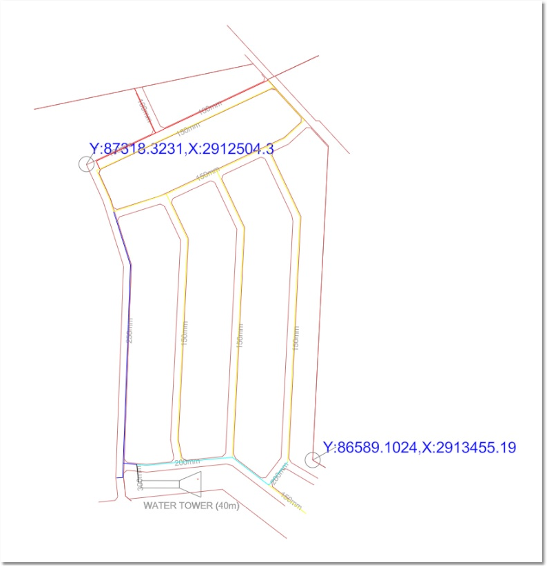
The different layers on this drawing are:
•TOWER - A diagram of the water tower
•PIPES300 - All 300 mm diameter pipes, and their associated text
•PIPES250 - All 250 mm diameter pipes, and their associated text
•PIPES200 - All 200 mm diameter pipes, and their associated text
•PIPES150 - All 150 mm diameter pipes, and their associated text
•PIPES100 - All 100 mm diameter pipes, and their associated text
•CADASTRAL - All cadastral background, and the text of the two known points
•0 - The (empty) default layer
The above can be verified by opening the Layer Control window via CAD > Tools > Layer Manager.
By moving the mouse cursor to the two known co-ordinate points, it can be determined that the drawing is not yet fixed to a proper co-ordinate system, since the given co-ordinates do not match those in the bottom right-hand boxes of the status panel. The drawing therefore first has to be fixed to a co-ordinate system, in order for pipe lengths, node elevations, etc. to be properly calculated and integrated with other data. This is achieved by geospatially fixing the drawing in two steps:
Step 1 (the hemisphere):
First click in an open space of the drawing (effectively making sure nothing is selected), and then set the User Coordinate System Preset to Southern Hemisphere by editing the CAD properties in the Edit box (located at the top right-hand corner), as follows:
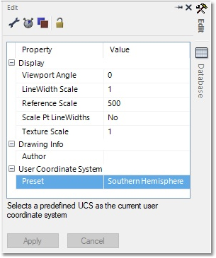
The coordinates (according to the Southern Hemisphere Surveyor coordinate system) are displayed on the bottom right-hand corner of the status bar. Note how Y now increases from East to West, and X from North to South.
Step 2 (scale and location):
Select CAD > Tools > Fix to Coordinates. You will then be prompted to convert the entire drawing. Select Yes. If you did not receive a prompt, a selection was active when starting the function. Exit the function and make sure nothing is selected before continuing.
Fixing Original Point A:
•Click on the mouse cursor icon situated to the right of the Original Point A text boxes. Zoom to the top left of the drawing by rotating the mouse wheel. Click on the first known point (point is marked in the drawing by a small circle). The original co-ordinate of the first known point A will hereby be filled automatically into the text boxes.
•On the keyboard, type: 87318.3231, 2912504.3, 0 into the corresponding Move To text boxes for Point A, which is the real world co-ordinate for this known point (as also annotated on the drawing).
Fixing Original Point B:
•Click on the mouse cursor icon situated to the right of the Original Point B text boxes. Zoom in to the bottom right of the drawing by rotating the mouse wheel. Click on the second known point (point is marked in the drawing by a small circle). The original co-ordinate of the second known point B will hereby be filled automatically into the text boxes.
•On the keyboard, type: 86589.1024, 2913455.19, 0 into the corresponding Move To text boxes for Point B, which is the real world co-ordinate for this known point (as also annotated on the drawing).
Finally, click on the dark green ("Yes") tick mark, located at the bottom right of the input template, to execute the coordinate transformation. The drawing is now fixed to the proper coordinate system. This can be verified by moving the mouse cursor to the two known coordinate points - the given coordinates will now match with those in the bottom right-hand boxes of the status panel.
Finally, the drawing can be saved (via CAD > Save Drawing As...), and the user can specify a new file name, such as ...\Wadiso 6 - Tutorial 2 drawing_fixed. The file Save as type should be set to Albion Drawing (*.abd). The new coordinates are hereby saved in the CAD drawing file, so that the drawing will automatically be fixed to the proper coordinate system when opened again.