For this part of the exercise, make only the layers PIPES100/-150/-200/-250/-300 visible, by navigating to CAD > Tools > Layer Manager, and setting the Visible check box for each layer.
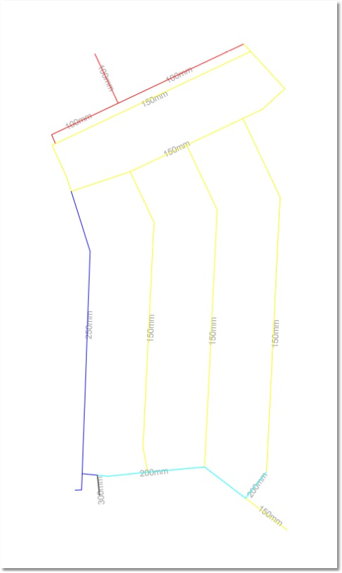
These layers represent a layout of the pipes to be modelled, but they are usually, at this stage, not suitable for modelling purposes. Some of the deficiencies in such a layout, which may typically be the result of data captured in a draughting office (where a picture only, and not a model, is the primary result), are:
•The lines may not snap properly onto each other.
•There may be long lines, which for the purposes of modelling should be split into shorter lines (representing pipes).
•The lines may not represent the pipes and nodes, which the modeller may want to see in a hydraulic representation of the network.
Therefore, in this part of the exercise, the lines will be redrawn in accordance with the modeller’s preferences, in preparation for capturing the model. The first step is to set up a relationship between the lines to be drawn and the diameters of the pipes which they will represent.
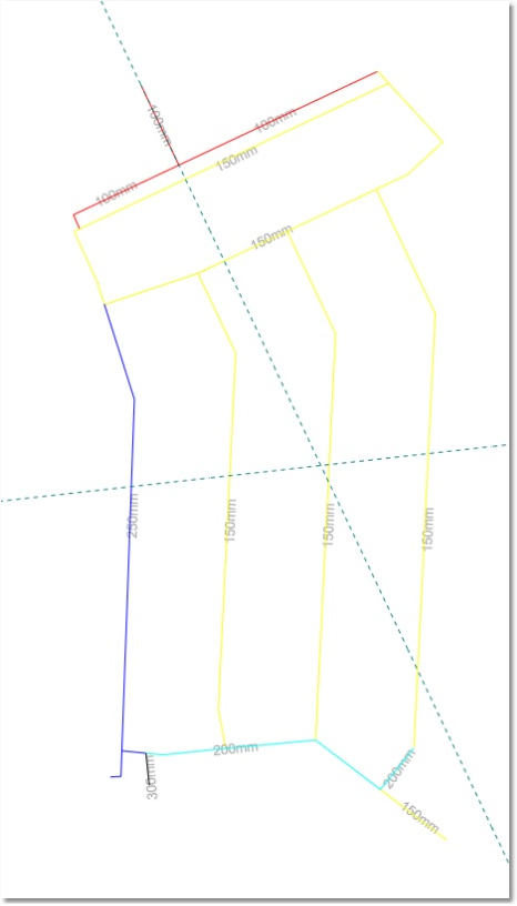
First, for the purpose of the exercise, a construction line (geometry line) will be used to define the position of the nodes along an approximate West-East axis. Select CAD > Draw > Construction Aids. This will initiate a prompt for two points through which to draw the construction line. Define them by typing on the command line bar, and pressing the Enter key to accept, the following (indicated in bold):
•87300, 2913000 for Point 1: Y 87300 X 2913000
•86400, 2912900 for Point 2: Y 86400 X 2912900
This will result in a construction line across the area (in an approximate West-East direction), more or less bisecting it in two equal portions. Now press the ESC key to end the construction line command. The intersection points of the construction line and the 'vertical' pipes, which run in a North-South direction, indicate (in this example) the endpoint of a model pipe, i.e. a node.
A construction line is also required to place a node on the northern most (top) of the two East-West 150 mm pipes, across the road from where the 100 mm pipes form a T-junction. This can be obtained by the following steps:
•Set the correct snap options on via CAD > Tools > Snap Settings, and check the following boxes: Vertex / End Point and Intersection.
•Select CAD > Draw > Construction Aids. The first and second point of the construction line will this time be defined by clicking on the two end points of the north-south 100 mm pipe (at the top end of the drawing). Now press the ESC key to end the construction line command.
This will result in a construction line, which is an extension of the 100 mm pipe. The intersection point of this construction line and the 150 mm pipe across the road indicates the position of a node.
Prior to capturing the model, the drawing can be saved (via CAD > Save Drawing As...) to ...\Wadiso 6 - Tutorial 2 drawing_fixed. The file Save as type should be set to Albion Drawing (*.abd).