Selected links/nodes can just as easily be updated in the Database box as individual links/nodes. Simply use the Albion selection tools to select certain links/nodes in the model and then conduct the edits on the selection set (i.e. group editing) via the Database box. The Albion selection tools consist of spatial selection functions as well as tabular selection functions such as filters, SQL queries, etc. (see Albion 6 CAD and Albion 6 GIS User Guides for more detailed description of these functions).
For instance: The user wants to assign an output of 40 l/s (i.e for steady state analysis); and a time pattern ID No. of “3”, to the Demand Category 1 ( i.e. for a subsequent time simulation) of all the nodes in a specific suburb/area of the system; and finally pipes along a certain pipe route should get assigned optimization group 6 (for a subsequent optimization). The procedure is as follows:
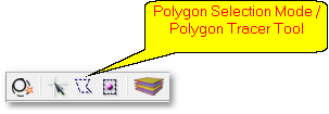
•Choose the standard Albion polygon selection mode and use the polygon tracer tool (see below) to select all model entities within a polygon traced around the suburb boundary. (After selection they will be highlighted and will constitute the model selection set).
• If the Database box is not already open, then hover over the ![]() Database icon to open it (note the box can also be pinned, see Albion 6 GIS User Guide). In the Database box, select from the Layer drop-down list the layer with extension .Wa_node(Node_Type).
Database icon to open it (note the box can also be pinned, see Albion 6 GIS User Guide). In the Database box, select from the Layer drop-down list the layer with extension .Wa_node(Node_Type).
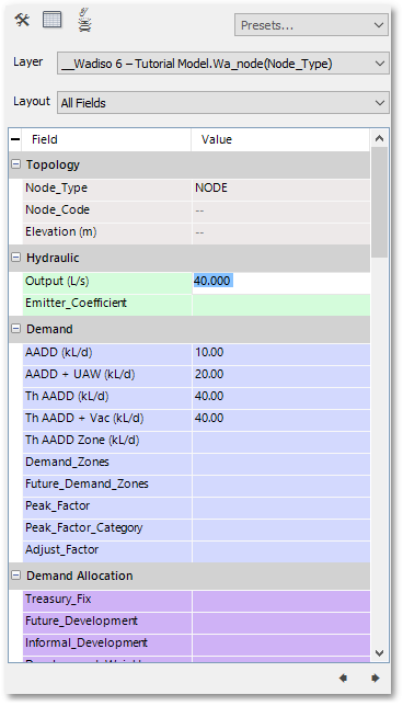
For a Steady State Analysis:
•In the Database box scroll to the Hydraulic tab (see screen-shot below).
•Enter a new value for Output, viz.. 40 l/s. Hereby all the nodes in the selection set will get assigned an output of 40 l/s.
•Notice the two dashes in the Database box at the Node_Code and Elevation fields. This is to indicate the selected nodes have different values for these data fields (i.e. instead of showing a particular Node_Code or Elevation value a dash is more appropriate to display).
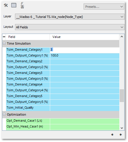
For a Time Simulation:
•In the Database box scroll to the Time Simulation tab (see screen-shot below).
•Enter a new value for Tsim_Demand_Category_1 , viz. 3 (for Time Pattern no. 3). Hereby all the nodes in the selection set will get assigned time pattern no. 3 for variations in their Demand Category 1.
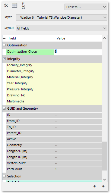
For an Optimization:
•Left-click on the first pipe along the route (of which optimization numbers are to be assigned) and then Ctrl+left-click on all other pipes along the route. (After selection they will be highlighted and will constitute the system selection set).
•In the Database box, notice how the Layer drop-down list automatically updates and displays the layer with extension .Wa_pipe (diameter).
•Now scroll to the Optimization tab (see screen-shot below).
•Enter a new value for Optimization_group, viz. 6 (for Group no. 6). Hereby all the selected pipes along the route will get assigned to optimization Group 6.