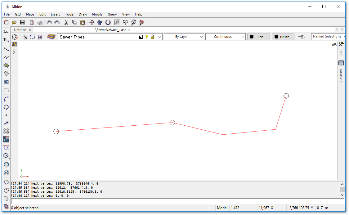
The second and last pipe of this small sewer network can now be drawn. The pipe will have two intermediate bending points and will be drawn by a polyline, which is a special line that can contain intermediate vertices and can thus have a zig-zag form.
•Click the ![]() Create a polyline tool in the left vertical toolbar. Click in centre of the second circle (end manhole of first pipe), to indicate the first vertex of the polyline. Notice how a temporary small circle will appear at the centre point, indicating the exact snap location.
Create a polyline tool in the left vertical toolbar. Click in centre of the second circle (end manhole of first pipe), to indicate the first vertex of the polyline. Notice how a temporary small circle will appear at the centre point, indicating the exact snap location.
•Follow the instructions at the bottom status screen. Indicate positions for the second and third vertex (i.e. the two intermediate bending points) by left-clicking with the mouse at locations approximately 20 m from apart. For this exercise the exact distances between the bending points are not important. Indicate the fourth vertex position by left-clicking (again approx. 20 m onwards) and then finish the operation by right-clicking.
•Your sewer network is now almost complete - only manhole identification text must still be defined: