We will now proceed with the drawing of pipes to connect the manholes. We will start with drawing a simple straight line to represent the first pipe in our network which is a straight pipe with no intermediate bending points. We have to set the snap setting first, so that the pipes will connect at the centre of the manholes:
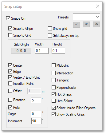
•Click the ![]() Configure snaps icon to open the Snap setup box and make sure that Center is checked:
Configure snaps icon to open the Snap setup box and make sure that Center is checked:
•Make the Sewer_Pipes layer active in the Layer Control box as described earlier for circle entities, or simply select Sewer_Pipes from the layer drop-down list:
![]()
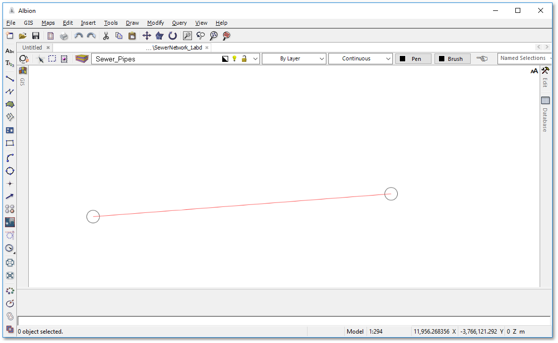
•Click the ![]() Create a line tool in the left vertical toolbar. Follow the instructions at the bottom status screen. Click in centre of the first circle (bottom left of screen), to indicate the first vertex of the line. Notice how a temporary small circle will appear at the centre point, indicating the exact snap location.
Create a line tool in the left vertical toolbar. Follow the instructions at the bottom status screen. Click in centre of the first circle (bottom left of screen), to indicate the first vertex of the line. Notice how a temporary small circle will appear at the centre point, indicating the exact snap location.
•Click now in the centre of the nearest circle to the right, to indicate the second (and final) vertex of the line. Right-click to finish. Your first sewer pipe of the network is now drawn (see below). You can save it if you want to prevent losing work as you go on.