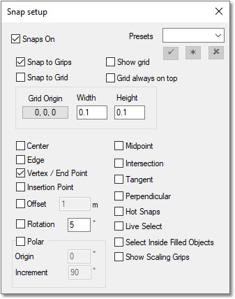
We will now start with an empty model, and demonstrate how to add entities. Before drawing pipes, let's first check that the Configure snaps settings are set-up correctly. Click on the icon under the current theme display:

Ensure that Snaps On is checked at the top left, and that at least Vertex / End Point has been checked. Finally, click on the top right X icon. This will ensure that when we draw pipes later, the starting/ending of the drawing procedure snaps accurately to the existing background:
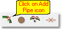
Now, to begin drawing pipes, click on the Add Pipe toolbar icon.
This launches the Quick Draw function, with which pipes can be added to existing nodes, or created from scratch. There are three different drawing modes, as indicated below. All three modes are used in this example.
![]()
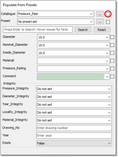
The Populate from Presets dialog box is also launched when adding pipes, and provides the user with an opportunity to override the default values, as set up in Model Settings, from a pipe database. Ignore this functionality, for this example, by unchecking the uppermost checkbox (remove the check mark), as seen in the image below, to only use the values as set up in Model Settings.
Hover the mouse cursor over the Quick Draw modes, and you will see that, from left to right, these are Single Mode, Connected Mode and Multi-Segment Mode.
![]()
First, select the Single Mode (leftmost option), in which each left-click with the mouse represents the placement of a node, and after two such left-clicks, a straight pipe is created between the two nodes. Therefore, move the mouse cursor to the centre position of the circle at Tank 1, and left-click. Then, move the mouse cursor to Node 2, and left-click at the centre of the circle again.
Now, select the Multi-Segment Mode (rightmost option), in which the first left-click either selects or creates the first node. Subsequent left-clicks only create vertices (also known as bend points or intermediates) on the pipe. The final left-click becomes the second node of the pipe, if followed by a terminating right-click. Therefore, move the mouse cursor to the position of Node 2, and left-click, followed by a left-click on the bottom left-hand vertex of Pipe 2, a left-click on Node 3, directly followed by a terminating right-click. You will see that a two-segmented pipe has been drawn.
Next, select the Connected Mode (middle option), in which every left-click, again, represents a node, but multiple straight pipes are repeatedly captured, until the process is terminated by a right-click. Therefore, move the mouse cursor to the position of Node 3, and left-click to represent the first node of Pipe 3. Then, move the mouse cursor to the position of Node 4, and left-click for the second node (and termination of definition) of Pipe 3. Node 4 in this mode is assumed to be the first node of the next pipe, i.e. Pipe 4. So, move to and left-click on Node 2 for the second node (and termination of definition) of Pipe 4. A final right-click stops this mode.
All four Pipes and four Nodes have now been created. Zoom in by using the mouse wheel to see that small nodes have, in fact, been generated.
The next sections will detail how to refine the model to match the values shown in the CAD drawing.