As for any CAD type drawing, there are a number of different layers. These layers can be viewed and manipulated by using the Layer Control dialog box via CAD > Tools > Layer Manager. For now, select OK to close this box.
The display of CAD lines representing pipes and other symbols can be improved on the drawing by making the lines somewhat thicker, through the following steps:
• Click on the layer drop-down list (located on the Quick Access Bar):
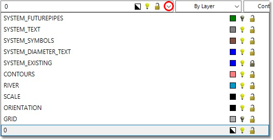
•First, click on the bulb icon next to the SYSTEM_FUTUREPIPES and GRID layers to hide them for now.
•Next, click on the lock symbol next to SYSTEM_EXISING to disable accidental selections on this layer.
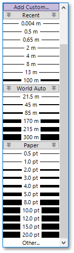
•Finally, right-click on the SYSTEM_EXISTING layer, and then while depressing the Ctrl key on the keyboard, right-click on the SYSTEM_SYMBOLS and SYSTEM_FUTUREPIPES layers to select all CAD items on these layers. Then, select from the line-width drop-down list (located on the Quick Access Bar) a 10 m width for all these elements. If the 10 m line-width option is not available in the list, you can add it manually:
oClick on the Other... option at the bottom of the list.
oEnter 10 under Custom Line Width, followed by selecting OK at the ensuing Line Width box:
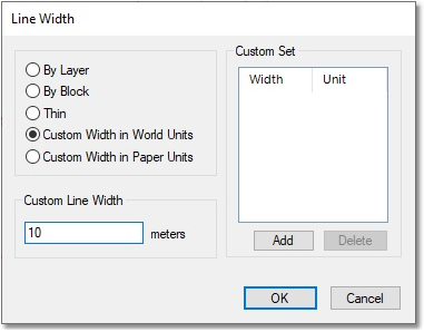
The line-width drop-down list will be updated, and the 10 m width will automatically be selected from the list, and applied to all the selected entities.