Open the drawing Documents\GLS\Wadiso\Wadiso 6 - My Tutorial Drawing_fixed.abd, which you geospatially positioned and saved previously. Alternatively, if you are not sure that your version of the drawing is absolutely correct, open Documents\GLS\Wadiso\Wadiso 6 - Tutorial Drawing_fixed_backup.abd, which was provided at program installation.
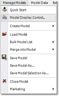
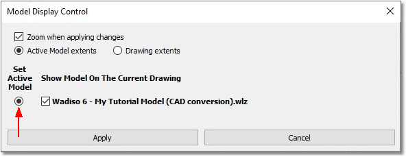
If saved correctly the previous time, this drawing should already have a geodetic projection, namely the same as for the model database. Note that the CAD/GIS in Wadiso/Albion can handle all types of projections, and converts all CAD/GIS objects ‘on the fly’, so that different projections can be seen simultaneously in the same project. In order to display the model on the drawing that was just opened, navigate to Manage Models > Model Display Control... Then, select Wadiso 6 - My Tutorial Model (CAD conversion).wlz as the Set Active Model (by clicking on the corresponding radio button), and select Apply. This procedure is illustrated by the following two screen-shots:
Open the Layer Control dialog box via CAD > Tools > Layer Manager. Set the visibility to off for all layers, except for the SYSTEM_EXISTING and SYSTEM_DIAMETER_TEXT layers, to make them the only visible layers of the drawing (leave “MODEL” layers switched-on as well). Select the SYSTEM_EXISTING layer, and click on the Make Current button, followed by selecting OK, to set this layer as the current layer of the drawing. Your CAD environment should now look like the one below.
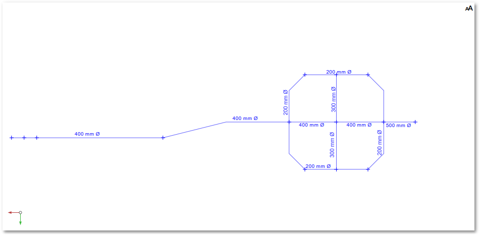
The small vertical blue lines on the drawing represent points where nodes are to be modelled in the system. There has to be a node where a pipeline changes diameter, where two or more pipes are joined (e.g. at a T-piece), or where water demand is to be modelled. Another reason for inserting nodes is to accurately represent the vertical profile of a pipeline, e.g. at gradient changes, or at high/low points on a pipeline. The layout of the model shows some pipes which run straight between nodes, and others with bend points (vertices). There are various diameters in the system, ranging from 200 mm Ø to 500 mm Ø.