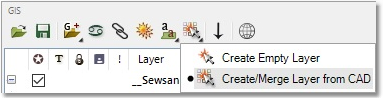
This exercise is to create a Wadiso model from the current CAD layers. This will entail converting the CAD layout to a GIS layer, and converting this layer, in turn, into a model. Select GIS > Data > Create/Merge Layer from CAD, or from the GIS Layer Manager toolbar, as shown below:
This will open the Import Cad window. Here, the user selects the layer to import the data from, as well as the destination layer and several import options.
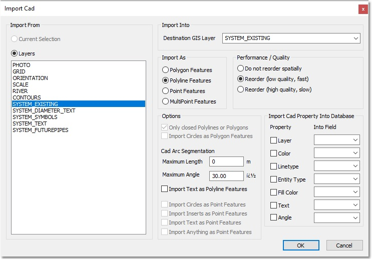
Select the layer (from the Layers list) that you want to import the data from. For this example, it will be the SYSTEM_EXISTING layer, since we are only concerned with GIS at this stage. Note that when the layer is selected, the Destination GIS Layer, Import As and Performance / Quality are assigned values – these should be SYSTEM_EXISTING, Polyline Features, and Reorder (low quality, fast), respectively. In order to accept these parameters, select OK.
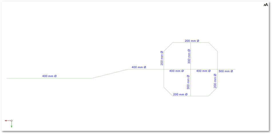
This should create a new GIS layer, and a notice will inform the user that 17 of 31 objects have been imported (all the lines), and that the source layer (the CAD lines that were previously blue) is now hidden. It should be noted that a new SYSTEM_EXISTING layer has instead been added to the GIS Layer Manager, and that our new layer has a red star. Also, the lines in the CAD environment will now have the colour automatically assigned to the GIS layer. This should leave the GIS Layer Manager (without the empty model) and CAD environment looking as follows:
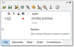
The red star indicates that the GIS layer has been created, but not yet saved.