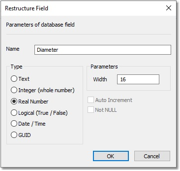
The next step is to add all the diameters to the respective pipes in our GIS model. In the GIS Layer Manager, right-click on the newly created GIS layer, labelled SYSTEM_EXISTING, and select Edit Database. This will open the database associated with the SYSTEM_EXISTING layer. Click on the top of the field labelled Field1. This will select and highlight the entire column. Right-click on the title, and select Rename / Restructure. This will open the Restructure Field window. Rename the field Name from Field1 to Diameter, and set the data Type to Real Number. The window should now look like the one below. Select OK to accept the changes. Select File > Close to dismiss the database window.
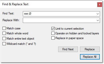
In order to fill this field with data, we will use the text on the CAD layer labelled SYSTEM_DIAMETER_TEXT. Unfortunately, these contain numbers, as well as alphanumeric characters (e.g. 400 mm Ø). In order to remove the letters, right-click > Edit Text in the CAD/GIS environment on any of the diameter text items to open the Edit simple text window, and copy (Ctrl + C) the text following the number (i.e. mm Ø). Dismiss the window (also make sure that nothing is currently selected in die CAD/GIS environment), and press Ctrl + A to select the entire drawing. Next, navigate to CAD > Edit > Replace Text. This will open the Find & Replace Text window. In the Find Text input box, paste the text we copied earlier, and in the Replace With box, enter a single space. Check the option Limit to current selection, and select Replace All. The window should look like the one below. A message should also be displayed to inform the user of how many labels were affected (11 in this case). Simply select OK, and dismiss the Find & Replace Text window.
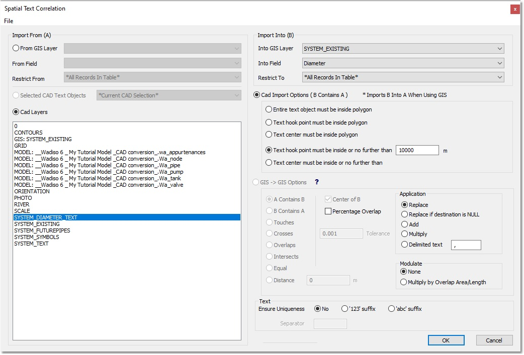
The next step is to fill the new Diameter field with the data as seen in the CAD window, using spatial correlation. Open the Spatial Text Correlation box via GIS > Tools > Spatial Correlation. On the Import From (A) side, toggle the Cad Layers option, and select SYSTEM_DIAMETER_TEXT as the layer to source data from. On the Import Into (B) side, select from the Into GIS Layer drop-down list the GIS layer labelled SYSTEM_EXISTING. Then, continue and specify the Diameter field from the Into Field drop-down list. In the area labelled Cad Import Options ( B Contains A ), select the fourth option – Text hook point must be inside or no further than. This specifies how far Albion must search to decide which data must be associated with which link. Enter 10 000, and select OK.