The existing model will now be extended to represent a future scenario. First, exit Wadiso 6 (if already open), and then start Wadiso 6. We will go through the exercise of customizing Render Settings again, assuming we have not previously saved the results.
Ensure that the background drawing, Wadiso 6 - Tutorial Drawing_fixed_backup.abd, has been opened. Do this by selecting CAD > Open Drawing, and selecting the file from the Documents\GLS\Wadiso\ folder.
Select View > Zoom to Drawing Extents to zoom to the entire drawing extent. Then, navigate to the CAD > Tools > Layer Manager, and hide the CONTOURS, GRID and SCALE layers for now by clicking Visible: Yes items to toggle them to No. Close the Layer Manager by clicking OK at the bottom right.
Then, load the last model, Documents\GLS\Wadiso\Wadiso 6 - Tutorial Model_backup.wlz (for example), from Manage Models > Load Model, and ensure that the circles for your nodes are about 100m in size by left-clicking on the Wa_node circle icons in the left-hand GIS layer panel, and setting:
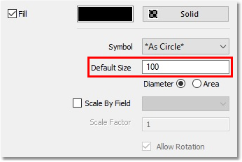
Hint: Should the Colour picker box appear on first click, simply repeat the procedure.
To temporary enlarge the text size of the pipes and nodes, proceed as follows:
•Right-click on the Wa_pipe layer in the left-hand GIS layer panel, and select Render Settings. Then, select the Labels tab.
•Then, select Labels from Field > Link_Code, Text Height: 200, Text Colour: Red.
•Then, press OK.
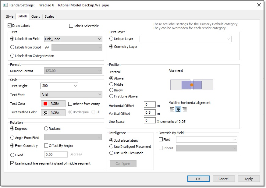
Repeat the procedure for Wa_node, but select Node_Code as field, 150 m as text height, and Black as colour.
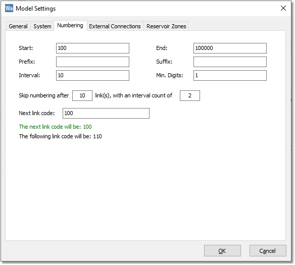
Next, navigate to Model Data > Model Settings, and then select the Numbering tab.
Then, on the Numbering tab, ensure that the Start and Next link code is set to 100, and the Interval is set to 10:
Also, on the System tab, set the Default Diameter to 200 mm, and the Default HW Coeff to 120. If your computer uses a different regional setting for a decimal point (e.g. a comma), leave this and do not change the other values below to decimal points:
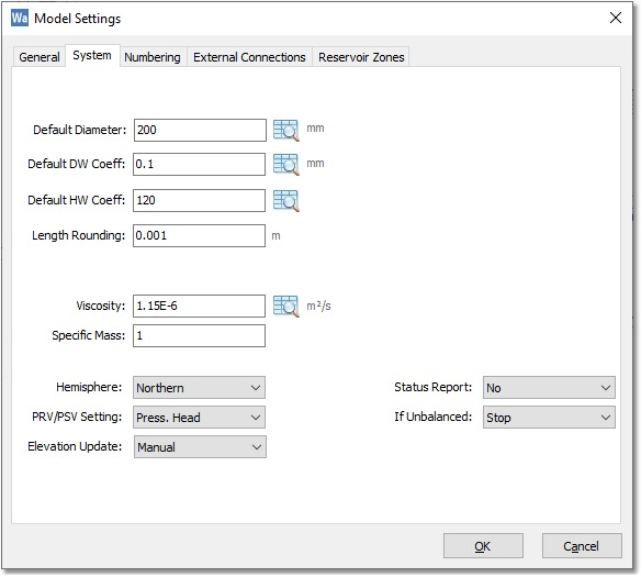
Now, select OK.
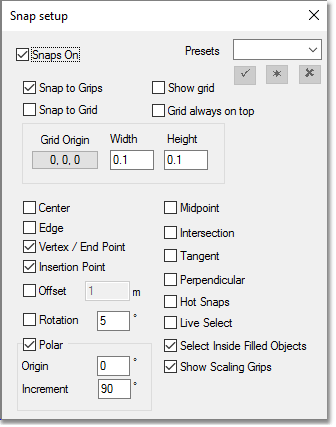
Then, select CAD > Tools > Snap Settings, and ensure that, at least, Snaps On and Vertex / End Point are ticked:
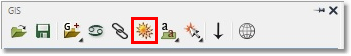
The pipes representing the future model, indicated in dotted lines, must now be captured. Add pipes directly to the hydraulic model, using the interactive Add Pipe functionality. Do this by selecting Model Data > Model Topology > Add Pipe (or find the Add Pipe icon in the top toolbar):
![]()
Ensure that you click on the Multi-Segment Mode button (third icon on the Add Pipe toolbar):
![]()
Then, zoom closer and draw the first parallel pipe (pipe 100) from the WTP to the upstream node of the pump station. Do this by first clicking on the node at the bottom of the WTP triangle, then click on the two intermediary points of the dotted line, and finally click on the upstream node of the P/S. As you approach existing nodes in the model, the symbology changes to a transparently filled circle. Now, right-click to terminate the addition of the new pipe.
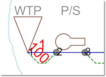
Click on the Add Pipe icon again, then click on the downstream side of the pump, node 3, then click on the two intermediary points along the next parallel pipe, and then left-click on node 4, under the text FEEDER MAIN (making sure the symbology changes to a transparently filled circle), followed by a right-click to terminate the addition of the parallel pipe.
Continue with the procedure for pipes 120, 130, 140, 150 (Parallel to 4, 5, 6 & 18 respectively). Pipe 18 is the final pipe which requires a parallel pipe. Right-click to terminate the Add Pipe function. Should the new pipe/node numbers not appear automatically, refresh the drawing by holding in the CTRL-key on the keyboard, and clicking on the Refresh All Layers in CAD Drawing icon in the left-hand GIS layer panel:
If you ever make a mistake, remember to use CAD > Edit > Undo to retrace your steps.
Now, navigate to Model Data > Model Settings again, and select the Numbering tab. Then, set the Start and Next link code to 1000.
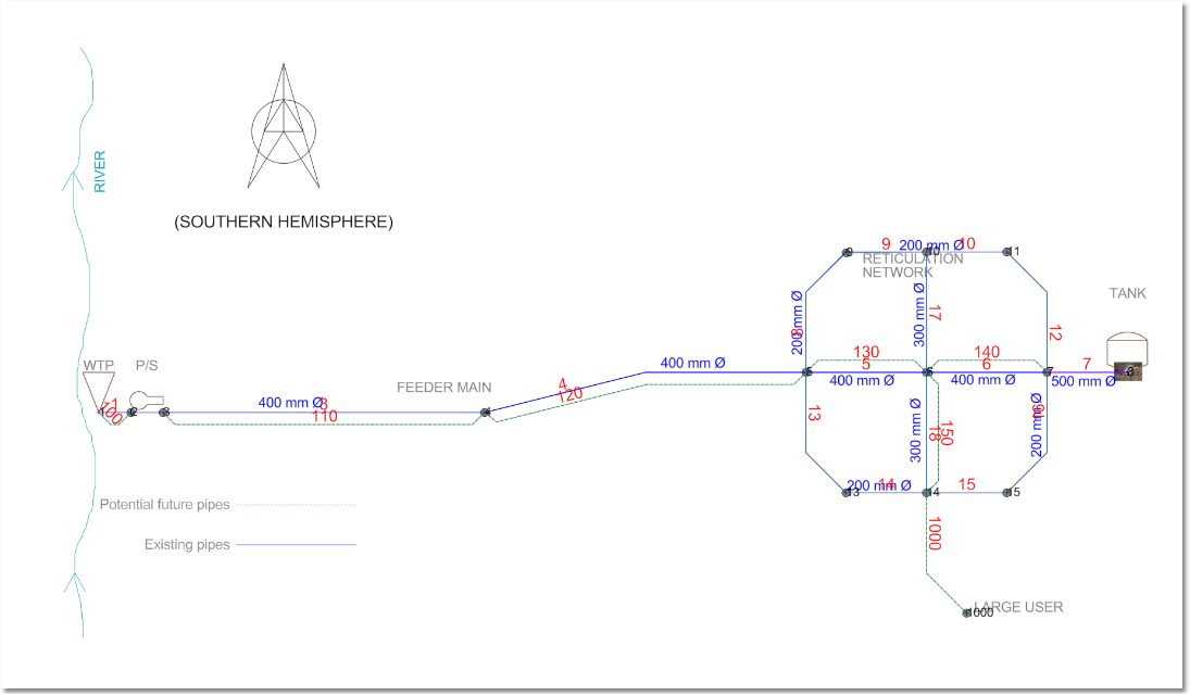
To capture the new pipe to the large user: Click on the Add Pipe icon again. Click very near node 14 (making sure the symbology changes to a transparently filled circle). Then, click on one intermediary point. Finally, click on the large user node, followed by right-clicking twice to conclude the operation.
Node 1000 is the only new node added. The full captured model should look like this:
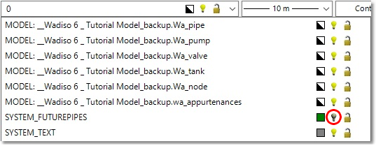
We can now hide the SYSTEM_FUTUREPIPES layer by switching off the bulb icon in the layer drop-down layer manager:
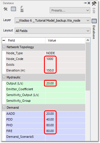
We still need to edit node 1000 to add additional information:
Click on the node, then move to the right-hand Database property editor.
Enter Elevation = 150 m and Output = 20 L/s.
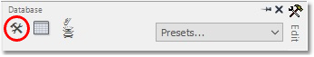
Now, let's first change the Display Names of the five Scenario fields for this exercise by clicking on the hammer-and-spanner symbol at the top left of the Database pane. Changes will not be saved, as they are only kept for the session. See Database Table Configuration (in the Albion Help) on how to save it to a file, or how to make it the default on your computer.
Then, change the Display Names accordingly, followed by selecting OK:
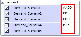
Then, enter the demands for the scenarios as follows:
AADD = 20
PDD = 40
PHD = 80
FIRE = 80
The future system has been captured with a provisional diameter of 200 mm. Ensure that the Output field is set for all nodes to the PH demand. Do this by first double-clicking on the Wa_node table in the left-hand GIS layer panel to open the table view of the node table, and then simply copying and pasting the PHD column over to the Output column.
The updated model can now be saved as Wadiso 6 - My Tutorial Future.wlz in the same folder, using Manage Models > Save Model As... (Correct file available as Wadiso 6 - Tutorial Future_backup.wlz).
The system can now be balanced (Analysis > Steady State > Balance). Then, click on Node 1000 (the new large user), and confirm that the Head is calculated as nearly (-)50 m!
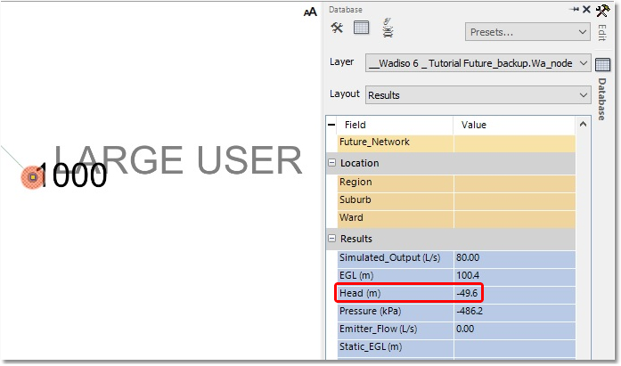
Typically, a minimum pressure of 20 m would be required, which means that this system clearly fails.
A design of the pipe sizes will be considered in the next section, to optimize the total cost.