Wadiso has a built-in module to automatically assign/update the nodal ground elevations based on surrounding elevation data. The module is based on the same principles used in triangulation routines found in most digital terrain modeling (DTM) software.
The following procedure can be followed for the nodal ground elevation assignment:
• A DTM, covering the network, must be active/load as described in Albion 6 CAD User Guide > Main Menu > Tools > DTM. Note the bulk of the DTM functions are covered in the aforementioned user guide.
•Finally, to update all the node elevations, go to DTM > Update Model Elevations:
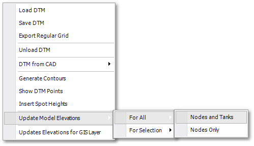
•As can be from the above screen-shot, there are various sub-menu options available for selecting which model entities to update, viz.: For All (i.e. whole network) or For Selection (i.e. a selection of the network only). Furthermore, you can choose between Nodes and Tanks or Nodes Only to update only those specific model entities.
• You may receive a warning that not all nodes could be updated. These nodes fall outside the area of the DTM, and their elevations must be set manually by accessing the node table via Model Data > Model Tables > Node.
There are a few other useful functions on the DTM menu:
•For example, a CAD drawing that contains contour polylines, with associated elevation text heights, can be used as input for a DTM. Apply the DTM > DTM from CAD > Assign Elevations to Polylines function and follow the prompts that appears in the status window (above the command line): Click on the first elevation text height and then click on its associated contour polyline. Repeat the procedure for all text/polyline pairs (the order does not matter, only make sure that you click on the correct text/polyline pairs). Right-click or press ESC when done.
•You can verify the above assigned polyline elevations by moving with the mouse pointer over a contour and observe the associated elevation Z- value at the bottom right of the display. Should this not work and only 0 elevation is shown, then ensure that the following snap settings are set (via CAD > Tools > Snap Settings): Snaps On, Edge, Vertex / End Point and Live Select.
•The DTM can now be built from the above text/polyline pairs. Select all contour polylines and then apply the DTM > DTM from CAD > Convert Polylines to DTM function: Enter a name or accept the proposed name for the new DTM object to be created. A DTM will then be generated with elevation points at all vertices of all selected polyline contours.
•With DTM > Insert Spot Heights, the elevation is calculated (by means of interpolation) at user-specified points (i.e. points identified by mouse click) and the elevation text is then written on the current layer at that exact location.
•The DTM can be saved via DTM > Save Dtm.
•The DTM > Export Regular Grid function can be used to export a regular grid of points with associated elevation data (interpolated from the DTM). You can specify a grid interval (i.e. distance in the X and Y directions) for the grid points to be exported. This grid interval can be different than the original DTM mesh points (in fact, the original DTM points are often irregularly spaced surveyor spot heights - this function is then very useful to obtain a regular elevation grid).
•With DTM > Unload DTM the current DTM is unloaded and removed from system memory.