We will now create circles to represent the sewer manholes of a sewer network section. The pipes connecting them, will be drawn in the following part of the exercise.
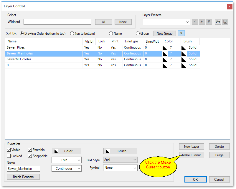
•Set the Sewer_Manholes layer as the current layer, by selecting the Sewer_Manholes layer in the Layer Control box. Click the Make Current button and finally, click OK:
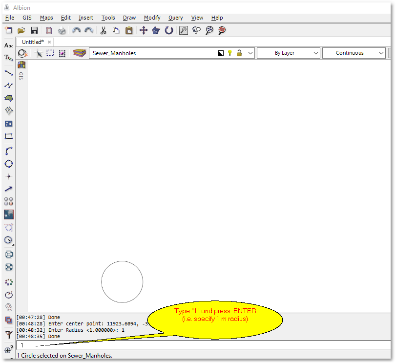
•Select the ![]() Create a new circle drawing tool from the left vertical toolbar (by left clicking on it). Then click in the drawing area somewhere at the bottom left. At the bottom status bar, enter 1 m for the radius. If the circle is not visible the you can select View > Zoom Extents (and zoom out again via the mouse central wheel, see viewing existing drawing for more zoom/pan functionality). Your first manhole circle should appear:
Create a new circle drawing tool from the left vertical toolbar (by left clicking on it). Then click in the drawing area somewhere at the bottom left. At the bottom status bar, enter 1 m for the radius. If the circle is not visible the you can select View > Zoom Extents (and zoom out again via the mouse central wheel, see viewing existing drawing for more zoom/pan functionality). Your first manhole circle should appear:
•Select the ![]() Create a new circle drawing tool from the left vertical toolbar again and draw two more manhole circles, approximately 50 metres space in between (you can use the X coordinate and Y coordinate at the bottom of the the screen to roughly gauge the distance in between, or apply the
Create a new circle drawing tool from the left vertical toolbar again and draw two more manhole circles, approximately 50 metres space in between (you can use the X coordinate and Y coordinate at the bottom of the the screen to roughly gauge the distance in between, or apply the ![]() Measure Distance tool and simply follow the instructions at the bottom status screen). For this exercise the exact distance between the manholes is not important.
Measure Distance tool and simply follow the instructions at the bottom status screen). For this exercise the exact distance between the manholes is not important.