The system data is now complete, except for one omission, namely the ground elevations of the nodes. For a small system like this one, it is feasible to individually edit each of the nodes. However, this becomes impractical when dealing with large systems. For this reason, a built-in module to automatically update ground elevations was developed, and will be demonstrated in this tutorial. It is based on the same principles used in triangulation routines, found in most digital terrain modelling (DTM) software.
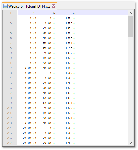
Firstly, a surveyed ‘spot-shot’ file covering the system area is required for the DTM routine. A typical file will have thousands of points, with a coordinate and elevation for each point. The spot shot points are normally captured on a fixed grid (e.g. 50 m x 50 m). The denser the grid of spot shot points, the more accurate the DTM. The survey file for this tutorial is Documents\GLS\Wadiso\Wadiso 6 - Tutorial DTM.yxz. You can view this file using any text editor (e.g. Windows’ Notepad). For this example file, a grid density of 500 m x 500 m was used. The first few lines in the DTM data file look like the following:
Now load the internal DTM file in Wadiso via DTM > Load DTM, and select the above survey file, followed by selecting Open. The DTM is then built in memory. You can verify the extent of the DTM by navigating to DTM > Show DTM Points, then selecting the relevant DTM file from the list of options in the Select DTM dialog box, followed by selecting OK, and then selecting an existing empty layer from the list of layers in the DTM Points Layer dialog box, such as layer “0” (also ensure that layer “0” is visible), followed by selecting OK. The elevation of individual points comprising the DTM mesh can be checked by hovering over them, and reading the YXZ values at the bottom right of the screen. You can now hide layer “0” again.
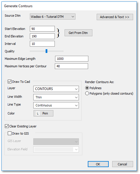
You can now create contours by using DTM > Generate Contours, which might first prompt the user to select the relevant DTM file from the list of options in the Select DTM dialog box, and then open the Generate Contours dialog box. In this dialog box, click on the Get From DTM button to set the start and end elevation. Setting the interval too small on a large DTM will result in large numbers of contour lines being generated. The Quality level affects the quality of the contour polyline generated. A lower quality level will cause the polylines to be approximated by rougher shapes, while a higher quality level will leave the polylines more detailed. The default settings should be adequate for most cases. Higher quality levels are to the right of the slider. The quality of the contours is also affected by the Maximum Edge Length setting. When two points on the DTM are further apart than the specified length, then a contour line will not be generated between them. This is often useful when it is necessary to avoid generating contours in sparsely populated areas of the DTM. Select OK to draw the contours.
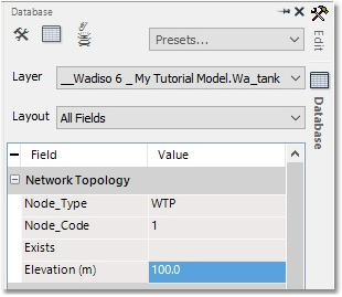
Finally, to update all the node elevations, navigate to DTM > Update Model Elevations > For All > Nodes and Tanks. Then, (if prompted) select the relevant DTM file from the list of options in the Select DTM dialog box. You will receive a warning that not all nodes could be updated, specifically Node 1 (the WTP). Since the node fell outside the area of the DTM, its ground elevation must be set manually to 100 m by click-selecting the node, and manually entering the ground elevation in the Elevation (m) field of the Database box:
The results of the process can now be viewed and checked by accessing the Database boxes of some of the individual nodes. For instance, access the Database box for Node 4 (centre of the feeder main). The Elevation (m) field value is now 110. The same for Node 6 (centre of distribution network) will show an Elevation (m) field value of 140.