GIS > Data > Assign Projection (select from Main Menu)
Assign Projection (select from Right-click Menu of GIS Layer Manager)
Assign projection to layers.
This function assigns a projection to layer(s), via settings specified in the Projections box.
Overview
Plane co-ordinates (i.e. projected co-ordinates) are ideal to use in CAD, GIS and other technical software applications, because the entities can be represented in a plane using standard rectangular x,y axis, which simplifies distance measurements and other spatial operations.
The shape of the earth can be approximated by a mathematical ellipsoidal function. Real world co-ordinates can then be expressed as ellipsoidal latitude (angular displacements measured in degrees north/south of the equator) and ellipsoidal longitude (angular displacements measured in degrees east/west of Greenwich meridian). These angular type of co-ordinates (also referred to as geographical co-ordinates), however, make the above-mentioned modelling of entities within technical software applications extremely complex. The latitude and longitude co-ordinates must therefore be projected onto a plane surface to obtain a more practical projected co-coordinate system (for use in the technical programs, such Wadiso and Sewsan). There is, however, always some distortion in this projection process, which can best be demonstrated by cutting a tennis ball in half and attempting to flatten it.
There are many different types of map projections available (preserving different properties), each will produce a different representation of the earth's surface. It is therefore important to choose the correct projection for the study area and type of application. Map projections can be grouped by either the preserved property or the projection surface. The following preserved property classes are available: Conformal (preserve local angles and shapes), equal area or equivalent (represent areas in correct relative size), equidistant (maintains consistency of scale along certain lines) and azimuthal (retains certain accurate directions). The other classification is based on the projection surface, viz. cylindrical, conic and azimuthal. This is basically the type of surface that is draped around the reference globe to construct the projection, viz. a cylinder, cone and for azimuthal it is a plane surface.
.
An important map projection parameter is the standard line. A standard line refers to the line of tangency between the projection surface and the reference globe. Standard parallel follows a parallel, whereas a standard meridian follows a meridian. There is no distortion (i.e. scale factor of 1) on this standard line during the projection process, because the standard line is the same as on the reference globe.
Central lines (also referred to as the central parallel and central meridian) define the centre of a map projection and can differ from the standard lines.
False easting and false northing can be assigned to shift the origin of the coordinate system (often done to avoid having negative co-ordinates).
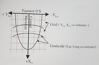
In South Africa the Gauss Conform Projection (an adaption of the Transverse Mercator) is often used for relative small study areas. It is a conformal projection (i.e. preserve local angles and shapes). The projected co-ordinates are commonly known as the “Lo. Co-ordinate system”
With the Gauss Conform Projection the equator will project as a straight line, at right angles to the central meridian (Lo.), but all other meridians and parallels will project as curved lines. The equator and the Lo. are the origins of the YLo and XLo axes of the plane rectangular co-ordinate system. The figure, below, shows the relationship between plane (Lo.) co-ordinates and geographical co-ordinates.
Only the area within one degree of longitude on either side of a central meridian (e.g. 19 degrees east) is projected accurately. The width of each segment or “belt” is therefore two degrees of longitude. If the study/site area does not fall within this belt, it is highly recommended to choose some other projection with a wider reach such as e.g. UTM (Universal Transverse Mercator).
Assign Projection: Function Description
The Assign Projection function opens the Projections box, in which the above-described projection parameters can be entered (see screen-shot below for the parameters of an Lo19 degree east system).

Note when accessing this function from the right-click menu of the GIS Layer Manager, then only the currently selected GIS layer will appear in the Projections box.
See Also