For the purpose of correctly capturing the model, the positions for the nodes are indicated by the black circles in the image below.
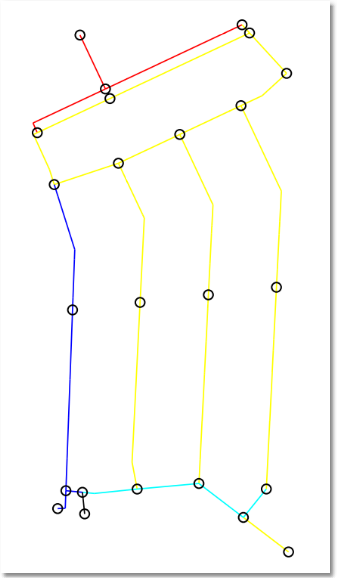
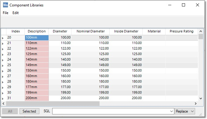
Use the above image of node positions when adding pipe and node entities to the model, by making use of the Single, Connected and Multi-Segment modes, as discussed before. Before adding the pipes, the pipe attributes can be set by selecting an option from the pipe catalogue database provided, in the Populate from Presets input form. Click on the ellipsis button (for the Catalogue option) to launch the Component Library, choose an option, and close to select.
For this example, if the pipes were properly added, as per the image of node positions, the process will result in 28 pipes and 24 nodes. If the user inserted more intermediary points instead of nodes, it will result in fewer pipes and nodes in the model, and vice versa. These are now ‘intelligent’ model elements, with data such as pipe diameter, coefficient, etc.
If the alternative way of compiling a model from CAD is preferred, the user can first create a new CAD layer, and then add lines and polylines in a similar fashion to the pipes, with endpoints at the node positions. The user can then follow the same procedure as before, i.e. convert the CAD Layer to GIS, and then use Manage Models > Merge into Model > Import from GIS.
The only outstanding data required to allow a hydraulic analysis are:
•The node elevations
•The output (water demand at nodes)
•Definition of Tank nodes
•Definition of special links, such as pumps, valves, etc.