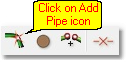
In order to start capturing/populating the empty model, navigate to Model Data > Model Topology > Add Pipe, or click on the Add Pipe toolbar icon.
This launches the Quick Draw function, with which pipes can be added to existing nodes, or created from scratch. There are three different drawing modes, as indicated below. All three modes are used in this example.
![]()
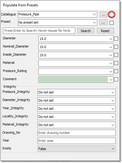
The Populate from Presets dialog box is also launched when adding pipes, and provides the user with an opportunity to override the default values, as set up in Model Settings, from a pipe database. Ignore this functionality, for this example, by unchecking the uppermost checkbox (remove the check mark), as seen in the image below, to only use the values as set up in Model Settings.
Hover the mouse cursor over the Quick Draw modes, and you will see that, from left to right, these are Single Mode, Connected Mode and Multi-Segment Mode.
![]()
First, select the Single Mode (leftmost option), in which each left-click with the mouse represents the placement of a node, and after two such left-clicks, a straight pipe between the two nodes is created. So, move the mouse cursor to the position of the WTP, and left-click. (The mouse cursor should auto-snap to the points on the background drawing – if not, ensure that the correct snap settings are switched-on ![]() ). Then, move to the upstream point (from node) of the P/S, and left-click again. Do the same from the upstream side of the P/S, to the downstream side (i.e. ‘to node’ of pump). (We will first capture the PS as a PIPE, and later change it to a PUMP). Also, left-click on the downstream side of the P/S, and then on the endpoint of the first 400 mm Ø pipe section.
). Then, move to the upstream point (from node) of the P/S, and left-click again. Do the same from the upstream side of the P/S, to the downstream side (i.e. ‘to node’ of pump). (We will first capture the PS as a PIPE, and later change it to a PUMP). Also, left-click on the downstream side of the P/S, and then on the endpoint of the first 400 mm Ø pipe section.
Next, select the Multi-Segment Mode (rightmost option), in which the first left-click either selects or creates the first node, and subsequent left-clicks create only vertices on the pipe, until the last left-click, which will be the second node of the pipe, if followed by a right-click. This is required for the next pipe, since it contains a vertex. First, left-click on the western end of the pipe, then on the vertex, then on the eastern end, and right-click to define this last click as the node.
Then, select the Connected Mode (middle option). Here, every left-click places a node, and multiple, connected straight pipes can be captured, until the process is stopped by a right-click. Use this mode to capture (in sequence) the next three pipes, up to the TANK. Left-click on the last node created, then on the point between the two 400 mm Ø pipes, then on the connection point between the 400 mm Ø and 500 mm Ø pipes, and finally on the tank (The tank is initially captured as a normal NODE, but we will later change it to a TANK). Finish off this process with a right-click.
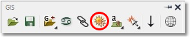
If, at any point, you cannot clearly see your newly added pipes, hold down the Ctrl key on the keyboard, while clicking on the Refresh All Layers in CAD drawing (sun) icon in the GIS Layer Manager:
Now use whatever mode you prefer, or is applicable, to (in sequence) capture the four pipes in the northern loop (from west to east), then the four pipes in the southern loop (from west to east), then the last two pipes in the middle of the system (from north to south).
All 17 existing links have been captured as pipes, with the default diameter of 100 mm, and 14 nodes have now been created (or captured). The pump link still has to be changed from a PIPE to a PUMP, and the WTP node still has to be defined as such, as for the TANK node. These changes will be undertaken in the following sections.
Your pipes and nodes should be numbered exactly as below (according to the numbering system defined in the Model Settings section). You can check this by switching off all the non-“MODEL:” layers in the Layer Manager.
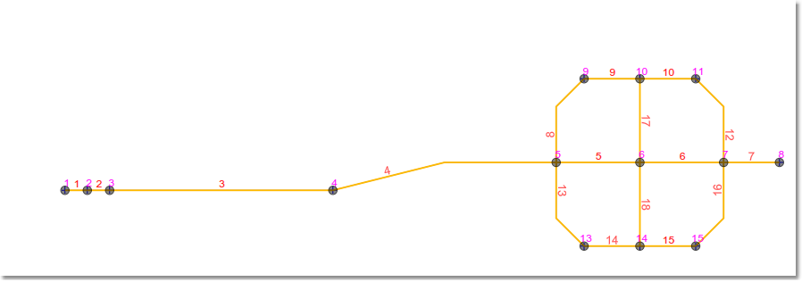
Note that link no. 11 will, according to the numbering system, not be assigned to the model (i.e. will be reserved for future use). The next sections will detail how to refine the model to match the values shown by the original CAD drawing.
However, if you ended up with a slightly different numbering system, but with nodes and pipes located at the same position, do not be concerned. Link and node numbers are not too important for the following sections; they are simply for reference in this tutorial. All future Link and Node numbers mentioned in this Tutorial will refer to the above image.