The Pump table is accessed via Model Data > Model Tables > Pump. Alternatively, the ![]() Pump Table toolbar button can be clicked.
Pump Table toolbar button can be clicked.
For each pump defined in the model, a line of system data (or pump properties) is required in the Pump table.
The most significant fields in the Pump table are described below. Note, the same field grouping is used as for the Pipe/CV table, except the Demand Allocation field group (for the Swift program) is not applicable for pumps:
•The same Network Topology data can be entered as described for the Pipe/CV table, but take note of the following:
oThe Link_Type in this case is PUMP.
oThe same Link_Code, From_Code and To_Code data can be entered as described for the Pipe/CV table.
oThe same Exists data can be entered as described for the Pipe/CV table.
Note: The from-to order of node codes is important, since the flow for Pumps is limited in a from-to direction.
•The required Hydraulic fields are:
oFlow1, Head1: A point on the pump characteristic curve (optional if a curve number is specified).
oFlow2, Head2: A second point on the pump characteristic curve (optional).
oFlow3, Head3: A third point on the pump characteristic curve (optional).
oCurve No.: This is an integer number referring to the ID of a pump curve, which is defined in the Curve table. The specified pump curve will override the information in the three flow/head data pairs (if any). By default, the curve no. is 0 (zero), indicating that the three flow/head data pairs define the curve.
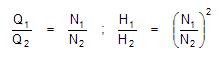
oRelative Speed (and On/Off Status): This is the rotational speed of the pump, relative to that speed for which the defined pump curve is valid. By default, this value is 1.0. For instance, if a value of 1.2 is specified, it implies that the rotational speed of the pump is 20% higher than the normal setting. The relationship between flow (Q) and head (H) at speeds N1 and N2 are calculated as follows by the program:
In order to stop a pump, enter a value of 0. The program will then treat the pump as a pipe with zero diameter, i.e. no flow will be allowed in either direction through the pump.
If three pairs of Flow/Head data points are entered, the program fits a parabolic curve through the three points to describe the pump’s relationship between flow and head, as follows:
Head = a*Flow2 + b*Flow + c
where a, b and c have to conform to the Pump curve requirements.
If only two points are entered, the program fits a straight line through the points (i.e. a = 0).
If only one point is entered, the program calculates a further two default points, in order to fit the parabola, viz.
Head2 = Head1 x 1.34
Flow2 = 0
Head3 = 0
Flow3 = Flow1 x 2.00
When a new pump is defined, it is automatically assigned a default pump curve through the points:
Head 1 = 134m = 440 ft
Flow 1 = 0 L/s = 0 gpm(US)
Head 2 = 100 m = 328 ft
Flow 2 = 100 L/s = 1585 gpm(US)
Head 3 = 0 m = 0 ft
Flow 3 = 200 L/s = 3170 gpm(US)
The actual flow characteristic curve can be entered/edited in the Pump table.
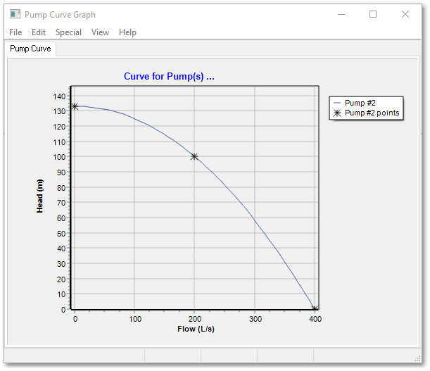
Pump characteristic curves can be viewed (in the Graph Editor) for a selected pump link via Model Data > Model Tables > Graph Selected Pump Curves, or by right-clicking on the pump link and using Selected Pumps (1) > Graph pump curves. The basic graph for a pump curve shows three points on the curve, and the mathematical line fitted through the three points. For pumps which are defined using a curve, the graph of lines connecting the points that define the pump curve is plotted.
A typical Flow-Head graph for a pump is shown below:
The above-listed Network Topology and Hydraulic field groups are the minimum required information for Wadiso, in order to perform flow and pressure calculations for the network.
•The other field groups (viz. Physical; Descriptive; Location; Results; Planning; Assets; Time Simulation Data; Optimization Data; Integrity; GUID and Geometry; and Model Functions) are the same as discussed for the Pipe/CV table.