The Valve table is accessed via Model Data > Model Tables > Valve. Alternatively, the ![]() Valve Table toolbar button can be clicked.
Valve Table toolbar button can be clicked.
For each valve defined in the model, a line of system data (or valve properties) is required in the Valve table.
The most significant fields in the Valve table are described below. Note, the same field grouping is used as for the Pipe/CV table, except the Demand Allocation field group (for the Swift program) and the Optimization fields are not applicable for valves:
•The same Network Topology data can be entered as described for the Pipe/CV table, but take note of the following:
oThe Link_Type in this case can be one of the following:
- FCV: a flow rate control valve,
- PRV: a pressure reducing valve,
- PSV: a pressure sustaining valve,
- PBV: a pressure breaker valve,
- TCV: a throttle control valve,
- GPV: a general purpose valve.
oThe same Link_Code, From_Code and To_Code data can be entered as described for the Pipe/CV table.
oThe same Exists data can be entered as described for the Pipe/CV table.
Note: The from-to order of node codes is important for PSVs, PRVs, PBVs, FCVs and TCVs, where flow is limited in a from-to direction. For GPVs, however, the from-to order is not important.
•The required Hydraulic fields are:
oDiameter: The inside diameter of the valve. This is only used for the calculation of flow velocities and minor losses.
The above are the minimum requirements in order to allow Wadiso to perform flow and pressure calculations for the network. When a new valve is defined, it is automatically assigned a default diameter of 100 mm and a default setting of:
- 100 m (for PRVs, PBVs and PSVs), or
- 10 (loss coefficient for TCVs), or
- 100 L/s (for FCVs), or
- ID = 0 (for GPVs), implying that the head loss curve has not been specified.
oSetting: This implies something different for each type of valve, viz. for:
- FCVs: The flow rate allowed through by the valve.
- PRVs: The pressure setting in liquid head (above ground level), which should be maintained at the downstream node.
- PSVs: The pressure setting in liquid head (above ground level), which should be maintained at the upstream node.
- PBVs: The amount of pressure in liquid head, which will be broken or dissipated by the valve.
- TCVs: The loss coefficient for the valve in the partially closed status, which is being modelled.
- GPVs: The integer ID of a curve in the Curve Table, which represents the relationship between flow and head loss for the valve.
The above are the minimum requirements in order to allow Wadiso to perform flow and pressure calculations for the network. When a new valve is defined, it is automatically assigned a default diameter of 100 mm and a default setting of:
- 100 m (for PRVs, PBVs and PSVs), or
- 10 (loss coefficient for TCVs), or
- 100 L/s (for FCVs), or
- ID = 0 (for GPVs), implying that the head loss curve has not been specified.
The actual diameters and settings can be entered/edited in the Valve table.
In addition to the above, the following optional Hydraulic parameters can also be specified:
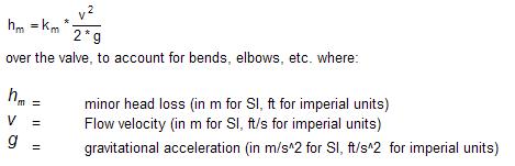
oMinor_Loss_Coefficient: A dimensionless constant value km which results in a head loss of:
oValve_Status: An indication whether the valve is “OPEN” or “CLOSED”. If “CLOSED”, the program will treat the valve as a pipe with zero diameter, i.e. no flow will be allowed in either direction through the valve.
oSetting_for_90m: The same Setting parameter as defined above, but specified for a specific 90 m pressure condition.
oEGL_for_90m: A specified fixed EGL for 90 m pressure condition.
•The other field groups (viz. Physical; Descriptive; Location; Results; Planning; Assets; Time Simulation Data; Integrity; GUID and Geometry; and Model Functions) are the same as discussed for the Pipe/CV table.