The Pipe/CV table is accessed via Model Data > Model Tables > Pipe/CV. Alternatively, the ![]() Pipe Table toolbar button can be clicked.
Pipe Table toolbar button can be clicked.
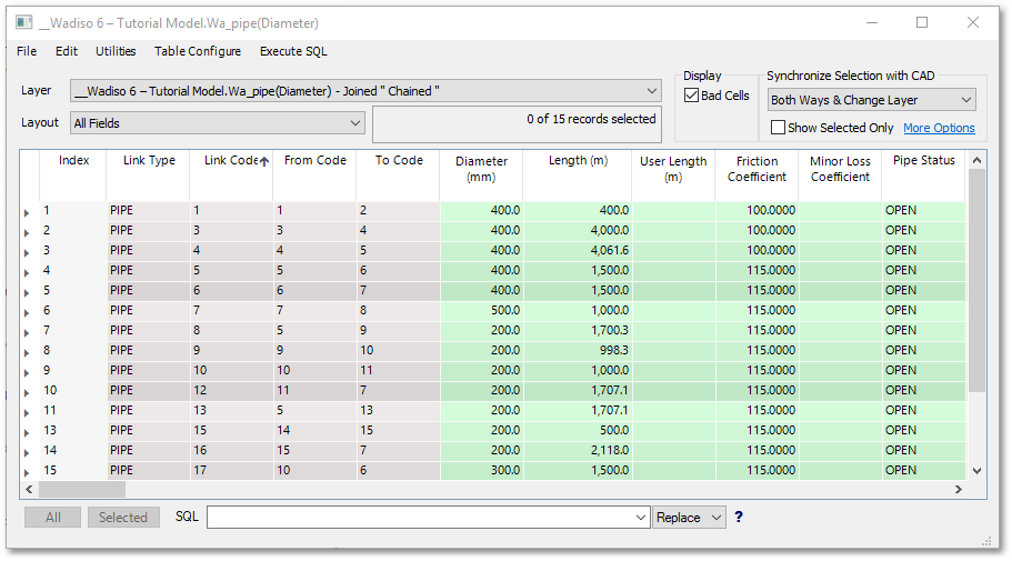
Pipe or check valve (CV) model data can be viewed/edited in the Pipe/CV table.
The various columns/fields in this table are grouped together in categories (displayed in distinctive colours), similar to the various groups of fields found in the Database box of an individual pipe (see Editing links and nodes in the Albion Environment). The grouping of fields and the formatting of the display (numeric format, background colour) can be set as a table “Layout” that can be saved and later retrieved. But, a variety of such layouts are predefined and loaded at program installation, e.g. a “default” layout focusing on the data, a “results” layout focusing on the flows and pressures, etc. Regular Wadiso users can pick an appropriate layout and do not have to bother with creating and specifying their own customised layout.
In the “default” layout, the first five columns (also referred to as a field group) display the Network Topology info. The next 6 Hydraulic columns are the system data fields required for hydraulic calculations. Then, there are Physical, Descriptive, Location, Results, Planning and Assets groups. These are followed by Time Simulation and Optimization columns, related to the respective specialised modules of the program. The final four groups are: Integrity; GUID and Geometry; Model Functions; and lastly Demand Allocation. The latter, viz. Demand Allocation columns relate to the integrated Swift water demand modelling program.
The most significant fields in the Pipe/CV table are described below, according to the above-mentioned field grouping:
•The following Network Topology data of the pipe/CV entities can be edited directly in this table (via above-mentioned first five columns, viz.: Link_Type, Link_Code, From_Code, To_Code and Exists), although it is recommended to rather perform topological edits with the special tools available in the Albion graphical environment (where there is also a better spatial overview of the network):
oLink_Type: The type of link can be any one of the following:
- PIPE: a pipe with constant diameter, roughness, etc.
- CV: a pipe with a check valve, which allows flow in one direction.
oLink_Code: A unique (text) code for the link. (The code is stored in the field as text - allowable inputs are any standard characters, such as numbers, or text, or a combination of numbers and text).
oFrom_Code: The (text) code of the node on the one end of the link. (Allowable inputs are the same as for the above-described Link_Code).
oTo_Code: The (text) code of the node on the other end of the link. (Allowable inputs are the same as for the above-described Link_Code).
oExists: Either True or False (binary field), depending on whether the link already exists, or is only planned for the future.
Note: The from-to order of node codes is important for CVs, where flow is limited in a from-to direction. For ordinary Pipes, however, the from-to order is not important.
•The following six Hydraulic data items required for Pipes/CVs can be entered/edited in this table:
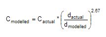
oDiameter: The inside* diameter of the pipe.
* For the Hazen-Williams flow equation, some users may prefer to set up the data with the nominal diameters of the pipes. Differences between nominal and inside diameters can then be accounted for by adjusting the C-values, as follows:
oLength: This is a length calculated internally by the program, based on the geographic route of the pipe/CV. The calculated length is only possible with Coordinate Mode ON, and the calculation is rounded off as per the Length Rounding setting in the System tab of the Model Settings dialog box.
oUser Length: This is an optional item, which, if entered, will override the calculated length that is based on the geographic route of the pipe/CV.
oFriction Coefficient: The roughness coefficient of the pipe, i.e. the C-value if the Hazen-Williams flow equation is selected, or the absolute roughness if the Darcy-Weisbach flow equation is selected. Selection of flow equation is effected through the General tab of the Model Settings dialog box.
oMinor Loss Coefficient: A dimensionless constant value km which results in a head loss of:
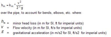
oPipe Status: “OPEN” or “CLOSED”. If closed, the program will assume a zero diameter for the pipe when performing the analysis, i.e. the pipe will act as an isolation valve.
The above-listed Network Topology and Hydraulic field groups are the minimum required information for Wadiso, in order to perform flow and pressure calculations. The next field groups are designated for user-specific data, analysis results, time simulation, optimization, geometry, selection and demand allocation. These are briefly discussed below:
•The field groups Physical, Descriptive, Location, Planning, Assets and Integrity are user-specific data, not relevant to the hydraulic calculations, but very useful for keeping record of the model entities. The Physical fields contain information on the pipe material, inside diameters, etc. The Descriptive fields contain information on e.g. the system name, a relevant comment, and the network name of the related pipe. The Location fields contain information on e.g. the region/suburb/ward name in which the pipe is located. The Planning and Assets fields are used for cost master planning. The Assets fields are used for asset management. The Integrity fields can hold information on the integrity of the data. The Multimedia field, in the Integrity group of fields, can contain hyperlinks to images, video files, and internet addresses. Hereby, useful additional information on the model entities can be viewed/accessed.
•The Results fields contain the model results after balancing the model, or after a time/water quality simulation, or after optimization of the model. These result fields are described in the relevant sections of this help manual.
•The Pipe & CV table also allows edits to the cost data, optimization data and time/water quality simulation data associated with each pipe or CV. Other, more specific, editors accessible from the Cost Data, Optimization Data and Simulation Data menus are, however, more appropriate for editing and entering these parameters. These data fields and properties are described in the relevant sections of this help manual.
•The GUID and Geometry fields are internal system fields, which store the automatically created Global Unique Identifiers (GUIDs) and the geometric characteristics of the entities (such as coordinates of From & To node, coordinates of vertices/intermediates, vertex count, length, etc.). These fields cannot be edited by the user.
•The Model Functions field group consists of four internal system fields viz. Cad_Sel (used to store the selection set, i.e. to keep track of which entities are selected), Source_Ratio, PartOfMP and Pipe_Redundancy.
•The Demand Allocation field group consists of Swift_Link (a field to link with the Swift water demand program) and Swift_Spread (used in the Swift program to...).
A typical data entry in the Pipe/CV table may look as follows (excerpt showing first 10 columns only):