The Node table is accessed via Model Data > Model Tables > Node. Alternatively, the ![]() Node Table toolbar button can be clicked.
Node Table toolbar button can be clicked.
For each node defined in the model, a line of system data (or node properties) is required in the Node table.
The most significant fields in the Node table are described below. Note, the same field grouping is used as for the Pipe/CV table, except for the new Demand field group (located just after the Hydraulic group) and the fact that the Planning field group is not applicable for nodes. Also note that the Demand Allocation field group (for the Swift program) contains more fields than in the Pipe/CV table, and the group is located just after the Demand field group:
•The following Network Topology data of the node entities can be edited directly in this table (via first four columns, viz.: Node Type, Node_Code, Exists and Elevation), although it is recommended to rather perform topological edits with the special tools available in the Albion graphical environment (where there is also a better spatial overview of the network):
oNode_Type: The type in this case is Node, i.e. an ordinary node at which the water pressure can fluctuate, and at which an output or an input can be modelled.
oNode_Code: A unique (text) code for the node. (The code is stored in the field as text - allowable inputs are any standard characters, such as numbers, or text, or a combination of numbers and text).
oExists: Either True or False (binary field), depending on whether the node already exists, or is only planned for the future.
oElevation: The ground elevation of the node expressed as height units above a datum level, typically mean sea level. By default, this elevation is zero when the node is initiated. Elevations can be updated by the DTM routines via DTM > Update Model Elevations.
•The required Hydraulic fields are:
oOutput: The water demand or rate of water extraction at the node. If a negative value is entered, it will be regarded by the program as input into the system.
oEmitter_Coefficient: The discharge coefficient for an emitter (e.g. sprinkler or nozzle) placed at the node. Units are L/s per m pressure drop (metric system), or USgpm per psi pressure drop (imperial system). The default value is 0.0 (zero), meaning there is no emitter present. If there are one or more emitters present in the system, the EPANet balancer must/will be used, since this feature is not supported by the Wadiso balancer.
When a new node is identified in the topology, it is automatically assigned a default output of 0.0, and default emitter coefficient of 0.0. The actual outputs and emitter coefficients can be entered/edited in the Node table.
•The Demand field group consists of the following fields:
oDemand Scenario: Five dedicated demand scenario fields are provided. These numeric fields allow input of alternative values for the demand at the nodes. The user can copy values from a scenario field to the actual Output column, using the standard Copy and Paste functions in the table. The heading for the fields can be customized (see Albion 6 GIS User Guide > User Interface Elements > Database Table).
oDemand_Zones: This field allows the user to specify a lengthy description of the ZONE in which the node is located. This field is stored as a memo field.
•The other field groups (viz. Demand Allocation; Physical; Descriptive; Location; Results; Assets; Time Simulation; Optimization; Integrity; GUID and Geometry; and Model Functions) are the same as discussed for the Pipe/CV table. The GUID and Geometry group, however, contains additional X, Y and Z fields to store the geographic location of the node. These X, Y and Z fields are also editable, although it is recommended to rather perform spatial/topological edits with the special tools available in the Albion graphical environment.
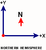
In the northern hemisphere, the X,Y coordinate axes are as follows:
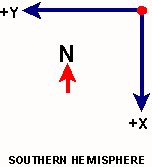
In the southern hemisphere, the Y,X coordinate axes are as follows:
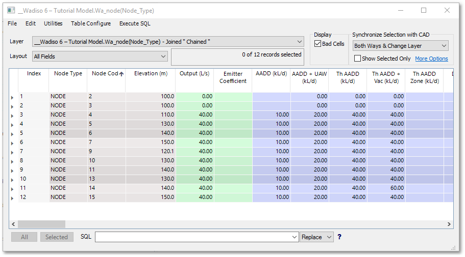
A typical data entry in the Node table may look as follows (excerpt showing first 10 columns only):